
Method and Apparatus for Remotely Monitoring the Condition of a Patient

a patient and monitoring system technology, applied in the field of patient monitoring systems, can solve the problems of reducing the utility of such systems, reducing the functional capacity of such systems, and systems that are obviously not suitable for ambulatory patients, and achieve the effect of enhancing functional capability and functional capability

Inactive Publication Date: 2009-05-07
CAREMATIX
View PDF9 Cites 52 Cited by
  • Summary
  • Abstract
  • Description
  • Claims
  • Application Information

AI Technical Summary

Benefits of technology

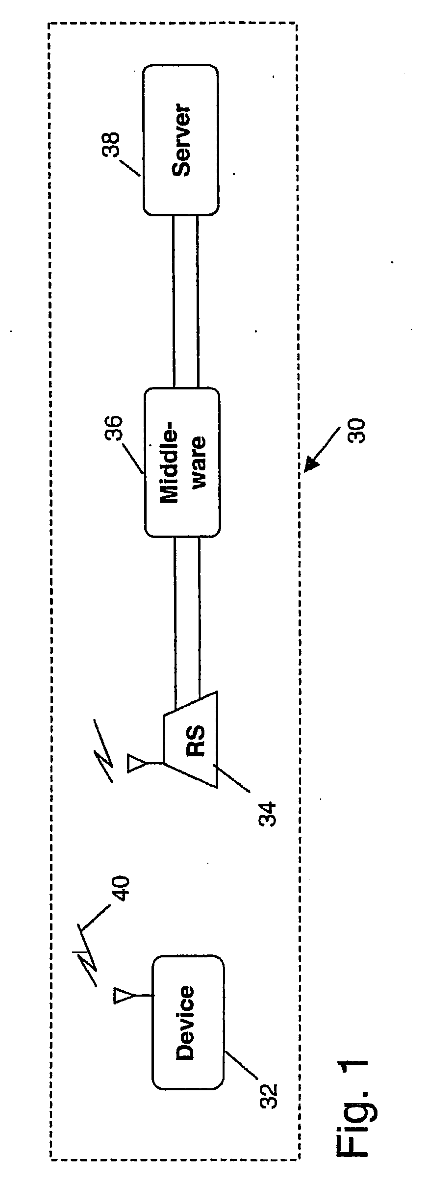
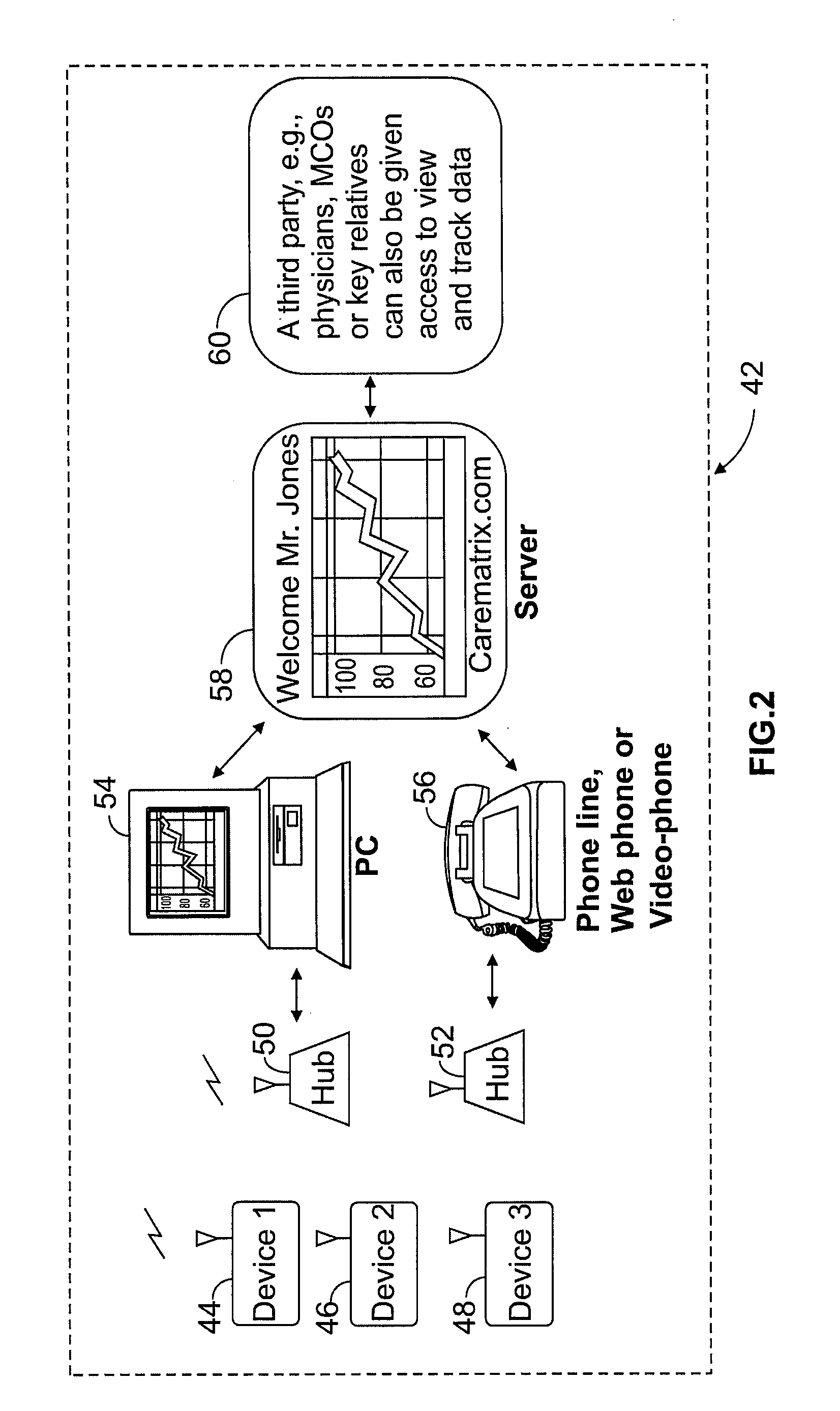
"The present invention is a patient monitoring system that can track various physiological characteristics of a patient, such as blood pressure and blood glucose levels, and transmit the data wirelessly to a local hub. The hub can then transfer the data to a remote server, which can be accessed by designated third parties like physicians or the patient themselves. The system also allows for enhanced functionality and trending of the physiological data, as well as automatic notification of patients or third parties when certain physiological characteristics exceed predetermined thresholds. Additionally, the system can provide reminders to patients to take readings."

Problems solved by technology

Healthcare costs have been increasing at a tremendous rate for the past decade, far exceeding the rate of inflation.
The fact that the patient monitors are hard wired to the local station significantly reduces the utility of such systems.
For example, such systems are obviously not suitable for ambulatory patients and many applications where it may be desired to remotely monitor the physiological characteristics of a patient outside of a non-clinical environment.
Such systems have been found to be far too complicated and difficult for elderly and critically ill patients.
Unfortunately, the functional capability of such systems is relatively limited.
For example, such systems only provide limited access to the patient data.
In addition, such systems can not be used to provide reminders to patients to take readings or provide messages to the patients or third parties when the physiological characteristics of a patient exceed predetermined thresholds.

Method used


Image

  • Method and Apparatus for Remotely Monitoring the Condition of a Patient
  • Method and Apparatus for Remotely Monitoring the Condition of a Patient
  • Method and Apparatus for Remotely Monitoring the Condition of a Patient

Examples


examples

[0289]Source code for the placeholder classes comprising the BOF is available. Accompanying that are two example packages: boexample1 and boexample2. These provide example implementations for a session BO and entity BO respectively. They illustrate the patterns and conventions required to create BOs and should be thoroughly studied.

[0290]Usage

[0291]In order to access a BO from calling code, the following example of a handler method for handling account events is illustrative:

     public  void  perform(PWMAppEvent  event)  throwsPWMAppEventException {  AccountEvent ae = (AccountEvent)event;   ...  switch (ae.getActionType( ))   {    case AccountEvent.CREATE_ACCOUNT:    {     try     {      UserHome userHome = BOUtil.getUserHome( );      User user = userHome.create( );      user.createAccount(ae.getUserId( ), . . .);      ...      }      catch (DuplicateKeyException dke)      {      ...      }       / / Catch more exceptions    }  } }

[0292]Deployment

[0293]Entries need to be created in t...


PUM


Abstract

A patient monitoring system provides enhanced functional capability relative to known systems and provides a wireless communication link between a patient monitoring device, worn by a patient, and a local hub. The patient monitoring system is adapted to monitor various patient physiological characteristics, such as blood pressure, pulse rate, blood glucose, weight, pulse oximetry and others. The data from the patient monitoring device is wirelessly transmitted to a local hub, which, in turn, is configured to automatically transfer the data to a remote server, for example, over a public or private communications network. In one embodiment of the invention, the server is configured as a web portal to selectively allow access to such patient physiological data by designated third parties, such as physicians, clinicians, relatives and the patient themselves.

Description

RELATED APPLICATIONS[0001]This is a continuation application which claims the benefit and priority of U.S. patent application Ser. No. 10 / 414,326, filed Apr. 15, 2003, which claimed the benefit of U.S. provisional application No. 60 / 372,894, filed on Apr. 16, 2002.BACKGROUND OF THE INVENTIONComputer Listing Appendix[0002]This application includes a Computer Listing Appendix on compact disc, hereby incorporated by reference.1. FIELD OF THE INVENTION[0003]The present invention relates to a patient monitoring system and more particularly to a patient monitoring system for monitoring various physiological characteristic data of a patient, such as blood pressure, pulse rate, blood glucose, weight and others, which wirelessly transmits such data to a hub, located near the patient, which, in turn transfers the data automatically to a remote server, for example, over a public or private communications network, which, in one embodiment, the remote server is configured as a web portal which s...

Claims


Application Information

Patent Timeline
Patent Type & Authority Applications(United States)
IPC IPC(8): A61B5/02A61B5/00A61B5/0205A61B5/021A61B5/087A61B5/117G06F19/00H04M11/00
CPCA61B5/0002H04L67/2838A61B5/021A61B5/087A61B5/117A61B5/1455A61B5/411G06F19/3406G06F19/3418G06F19/3425G06F19/3487G06F19/366G06Q40/08G06Q50/22G06Q50/24H04M11/007H04L67/025H04L67/28Y10S128/92Y10S128/903Y10S128/905Y10S128/904A61B5/02055H04Q2209/40H04Q9/00H04Q2209/823G16H80/00G16H40/63G16H15/00G16H10/40H04L67/567H04L67/56
Inventor KHANUJA, SUKHWANT SINGHGARG, SANDEEPSINGH, IRWIN PREET
Owner CAREMATIX
Learn More