
Method for reducing peak-to-average power ratios in a multi-carrier transmission system

a transmission system and multi-carrier technology, applied in the field of communication systems, can solve the problems of reducing power efficiency and average power emission, high peak-to-average power ratio, and reducing power efficiency and average power, so as to reduce the peak-to-average power ratio (par), reduce redundancy, and reduce the effect of par for multi-carrier transmission system

Inactive Publication Date: 2010-03-09
NAT SEMICON CORP
View PDF7 Cites 6 Cited by
  • Summary
  • Abstract
  • Description
  • Claims
  • Application Information

AI Technical Summary

Benefits of technology

[0010]In accordance with the present invention, a method for multi-carrier transmission are provided that substantially reduce peak-to-average power ratio (PAR) with low redundancy. In particular, a portion of the subcarriers in a multi-carrier signal are multiplied by −1 before transmission and again after being received, allowing the PAR for the multi-carrier transmission system to be considerably reduced.
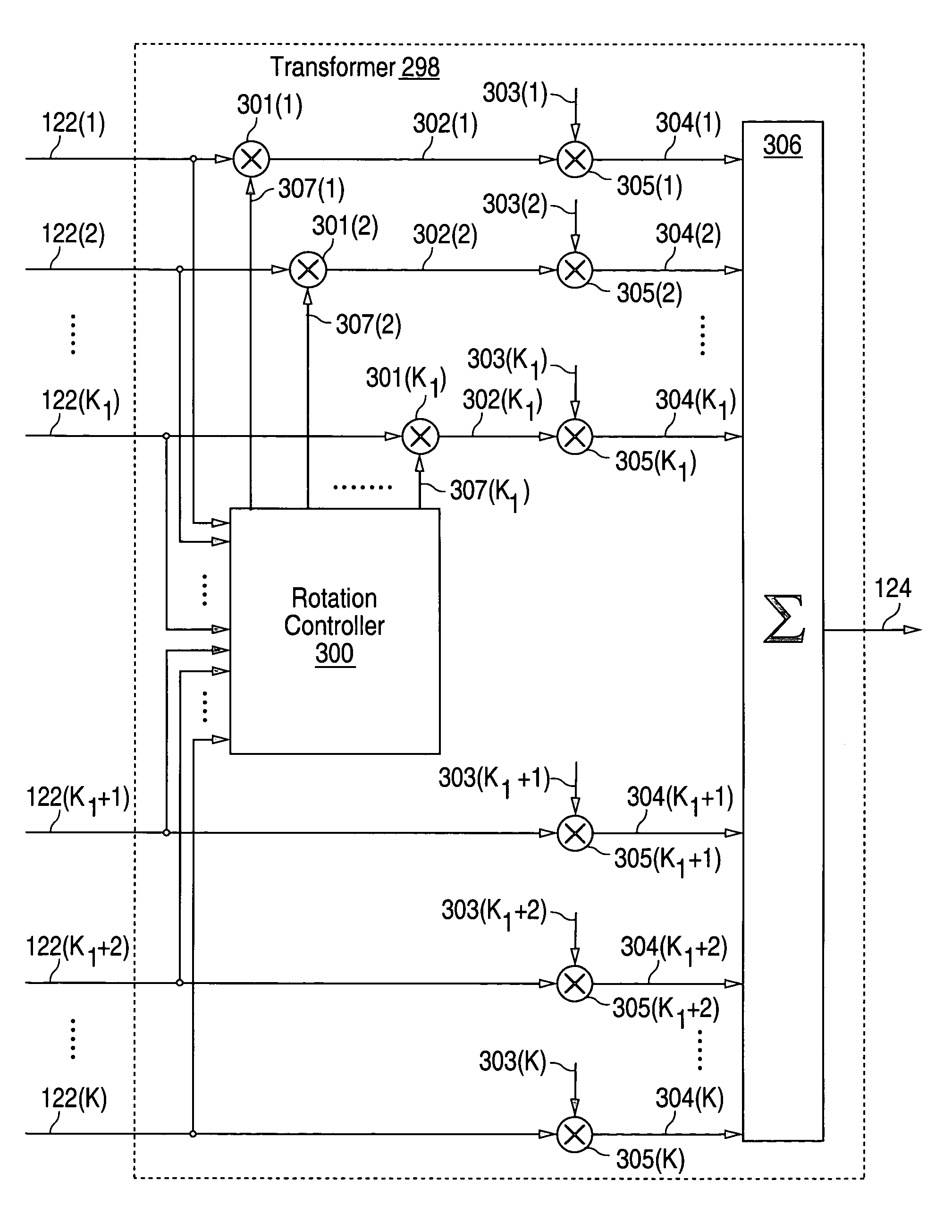
[0011]According to one embodiment of the present invention, a method for reducing peak-to-average power ratios in a multi-carrier transmission system is provided. The method includes receiving a plurality of modulator outputs. The modulator outputs comprise PAR subcarriers and non-PAR subcarriers. A subset of the PAR subcarriers is selected to be rotated by 180°. The selected subset of PAR subcarriers is rotated by 180°. A transformer output is generated based on the modulator outputs using the rotated PAR subcarriers, the unrotated PAR subcarriers and the unrotated non-PAR subcarriers.
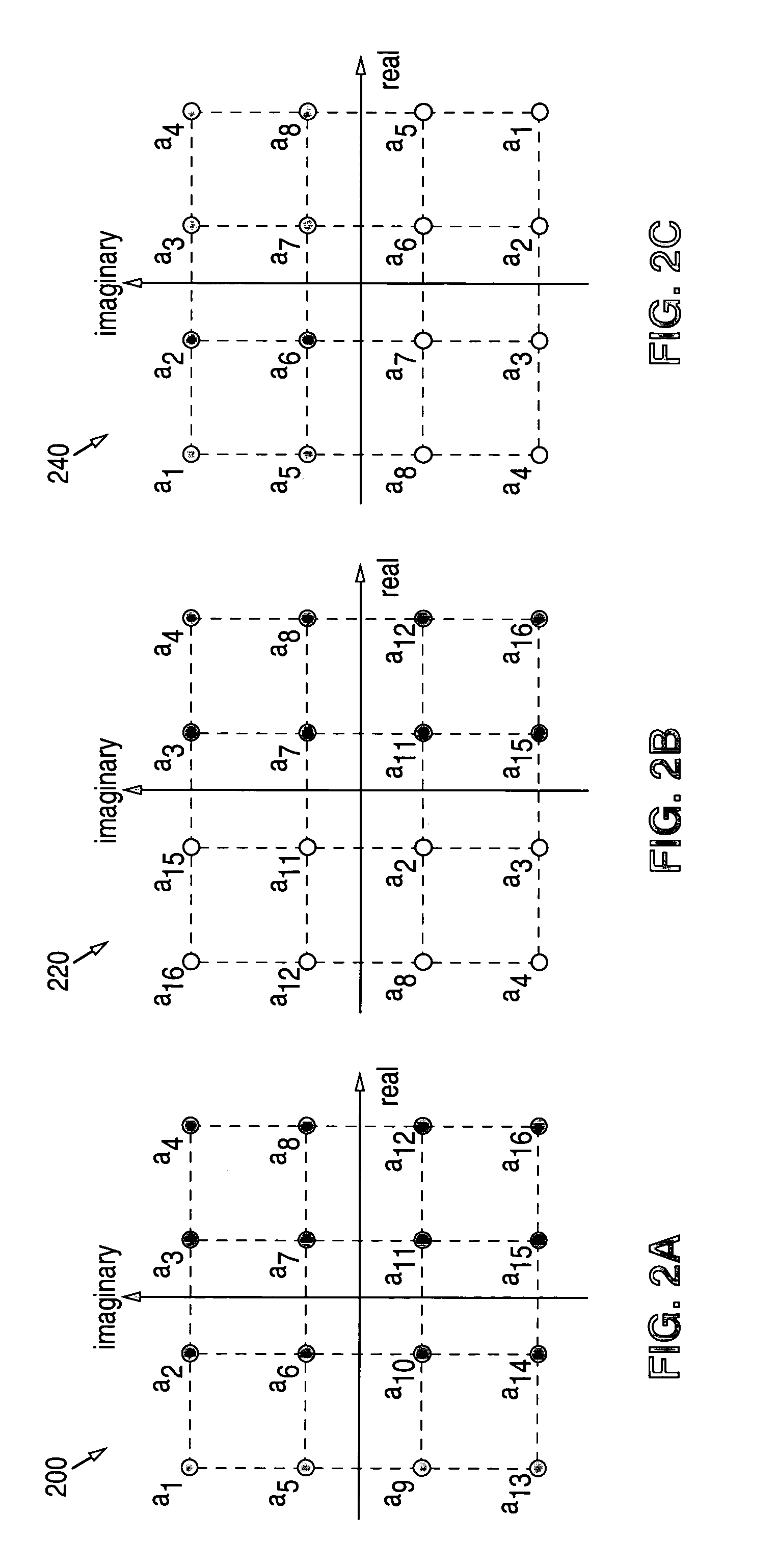
[0012]Technical advantages of one or more embodiments of the present invention include providing an improved method for reducing peak-to-average power ratios (PARs) in a multi-carrier transmission system. In a particular embodiment, redundancy to reduce PAR is introduced by reducing the constellations corresponding to a subset of subcarriers. Those subcarriers are called “PAR subcarriers.” The constellations corresponding to the PAR subcarriers must be higher than binary and invariant under multiplication by −1. Examples of these constellations include, but are not limited to, Quadrature Phase Shift Keying (QPSK) and Quadrature Amplitude Modulation (16-QAM or 64-QAM).
[0016]Other technical advantages of the method in the present invention include high PAR reduction in relation to redundancy. If a multi-carrier system has K subcarriers, each subcarrier has a 2b-QAM constellation, and K1 subcarriers are assigned to be PAR subcarriers, then the redundancy becomes

Problems solved by technology

However, multi-carrier transmission systems generally have a high peak-to-average power ratio (PAR), which is undesirable.
However, peak power is limited by frequency regulation agencies, such as the Federal Communication Commission in the United States.
Due to realization limitations, multi-carrier signals are typically amplified with a large back off in radio frequency power amplifiers.
This reduces both the power efficiency and the average power emission, resulting in a decrease in the transmission range.
However, clipping causes in-band and out-of-band distortion which degrades the transmission performance.
Scrambling methods, such as selected mapping and partial transmit sequences, do not guarantee a PAR ratio below some low level.
However, Reed-Muller codes result in a considerable data rate reduction as the number of subcarriers increases.
That is, low PAR implies small coding distance, which is undesirable, and large coding distance implies high PAR, which is also undesirable.
However, this method selects redundant bits to reduce PAR within the structure of the used convolutional coding and hence may limit the achievable PAR reduction per the number of redundant bits.
Finally, a part of its complexity in the transmitter comes from the redundancy calculation according to a convolutional decoding structure.

Method used


Image

  • Method for reducing peak-to-average power ratios in a multi-carrier transmission system
  • Method for reducing peak-to-average power ratios in a multi-carrier transmission system
  • Method for reducing peak-to-average power ratios in a multi-carrier transmission system

Examples


Embodiment Construction

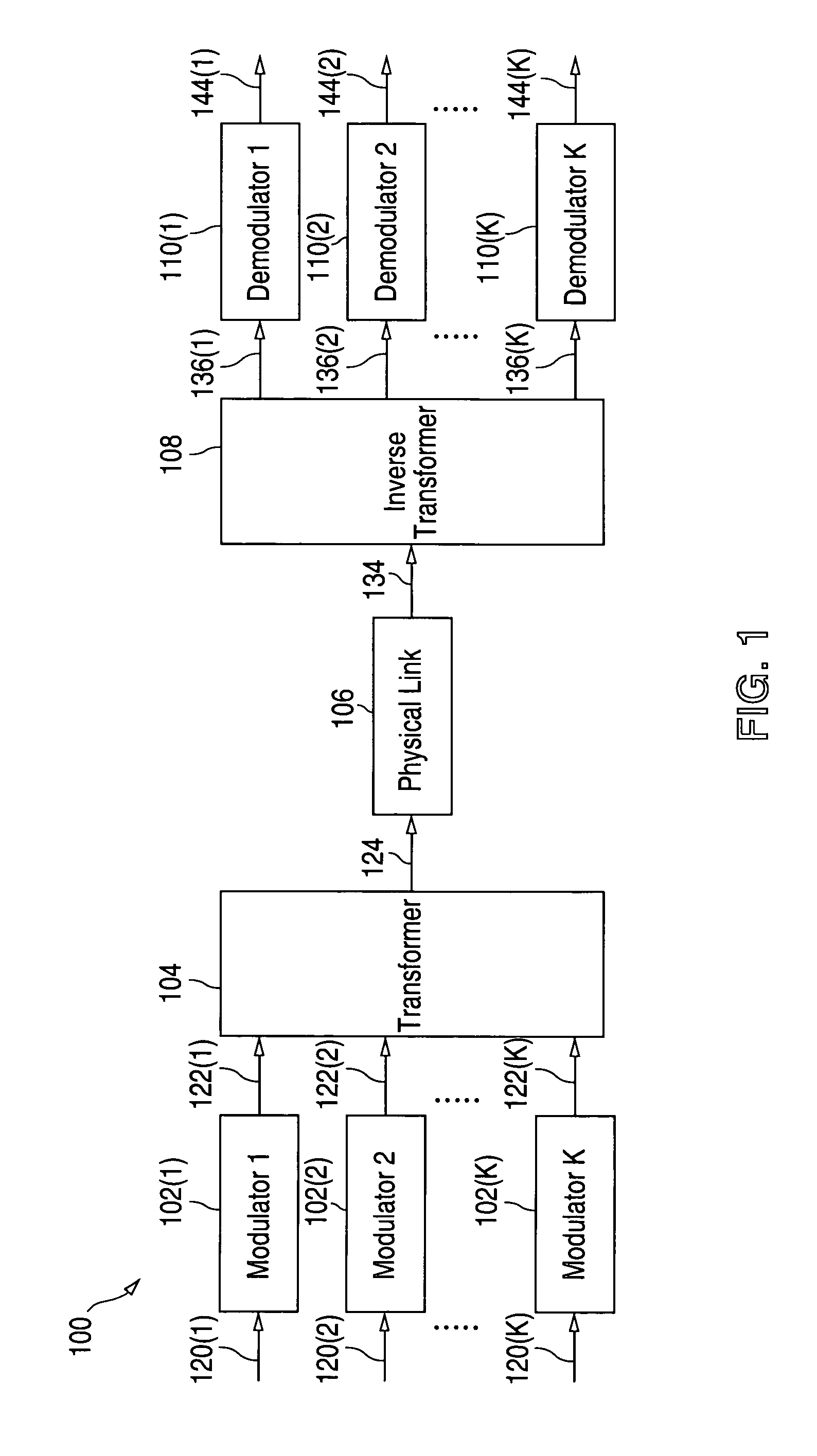
[0031]FIGS. 1 through 9, discussed below, and the various embodiments used to describe the principles of the present invention in this patent document are by way of illustration only and should not be construed in any way to limit the scope of the invention. Those skilled in the art will understand that the principles of the present invention may be implemented in any suitably arranged multi-carrier transmission system.

[0032]The embodiments and explanation provided below describe a peak-to-average power ratio (PAR) reduction technique that may be implemented in a multi-carrier transmission system. The description includes a basic realization of multi-carrier transmission systems for precise and clear explanation. Therefore, some techniques, which can be employed together with the PAR reduction technique described in this method, are omitted from the description. For example, the following techniques are not discussed: pilot subcarriers for accurate frequency / phase synchronization, c...


PUM


Abstract

The present invention provides a technique to reduce peak-to-average power ratio (PAR) of multi-carrier transmission systems. A non-empty subset of the subcarriers includes “PAR subcarriers.” The PAR subcarriers have constellations obtained by reducing a constellation that is higher than binary and invariant under multiplication by −1, so that an element is in the reduced constellation if and only if its negative is not. In this way, only one bit per PAR subcarrier is used for PAR reduction. The technique addressed in this invention multiplies a subset of the PAR subcarriers by −1 to reduce PAR at each multi-carrier symbol transmission. A method or apparatus is operated to select the subset of PAR subcarriers to be rotated. The receiver identifies the PAR subcarriers and estimates the subcarriers multiplied by −1 according to the reduced constellations and the received samples.

Description

[0001]This application is a continuation of prior U.S. patent application Ser. No. 10 / 195,287 filed on Jul. 15, 2002 now U.S. Pat. No. 7,139,322.TECHNICAL FIELD OF THE INVENTION[0002]The present invention relates generally to communication systems and, more particularly, to a method for reducing peak-to-average power ratios in a multi-carrier transmission system.BACKGROUND OF THE INVENTION[0003]High-speed data communication may be provided through the use of multi-carrier transmission systems. However, multi-carrier transmission systems generally have a high peak-to-average power ratio (PAR), which is undesirable. PAR increases in proportion to the number of subcarriers and the order of constellations. However, peak power is limited by frequency regulation agencies, such as the Federal Communication Commission in the United States. Moreover, a high PAR corresponds to a relatively wide dynamic range in transceivers. Due to realization limitations, multi-carrier signals are typically ...

Claims


Application Information

Patent Timeline
Patent Type & Authority Patents(United States)
IPC IPC(8): H04K1/10H04L27/28
CPCH04L27/2621
Inventor NERGIS, AYDIN
Owner NAT SEMICON CORP
Learn More