Keyless adjusting mechanism for chain saw

a chain saw and adjusting mechanism technology, applied in band saws, metal sawing accessories, manufacturing tools, etc., can solve the problems of inconvenient twisting of knobs and complicated structure of conventional adjusting mechanisms, and achieve the effect of simple structur

Inactive Publication Date: 2010-03-16
HUSQVARNA AB +1
View PDF13 Cites 14 Cited by
  • Summary
  • Abstract
  • Description
  • Claims
  • Application Information

AI Technical Summary

Benefits of technology

[0005]An objective of the present invention is to provide an adjusting mechanism for a chain saw, which has simple structure and is laborsaving for adjusting a tension of a chain.
[0007]The adjusting ring has a knob recess for receiving the knob. The knob has a through hole formed on a first end surface thereof corresponding to the knob recess of the adjusting ring, a positioning block disposed in the through hole, and a spring mounted between the positioning block and the knob recess of the adjusting ring for pushing the positioning block to project through the through hole. The knob further has a handle slot for receiving the handle. An end surface of the handle corresponding to the handle slot has a concave recess formed on respective sides thereof, in which the concave recess is biased against the positioning block. Moreover, a bottom surface of the handle slot is an inclined surface, whereby the handle can prevent from being obstructed by the protection cover when it is extended for operation.

Problems solved by technology

The conventional adjusting mechanism has a complicated structure, and has a knob that is inconvenient to twist.

Method used


Image

  • Keyless adjusting mechanism for chain saw
  • Keyless adjusting mechanism for chain saw
  • Keyless adjusting mechanism for chain saw

Examples


Embodiment Construction

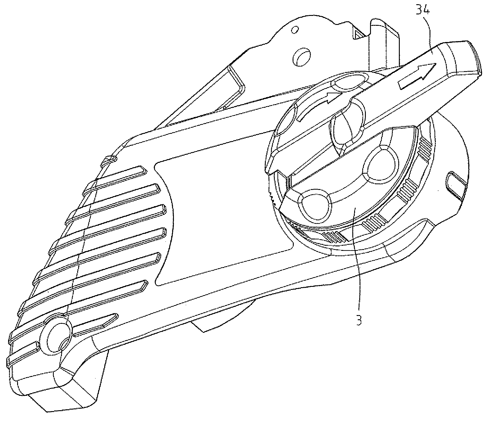
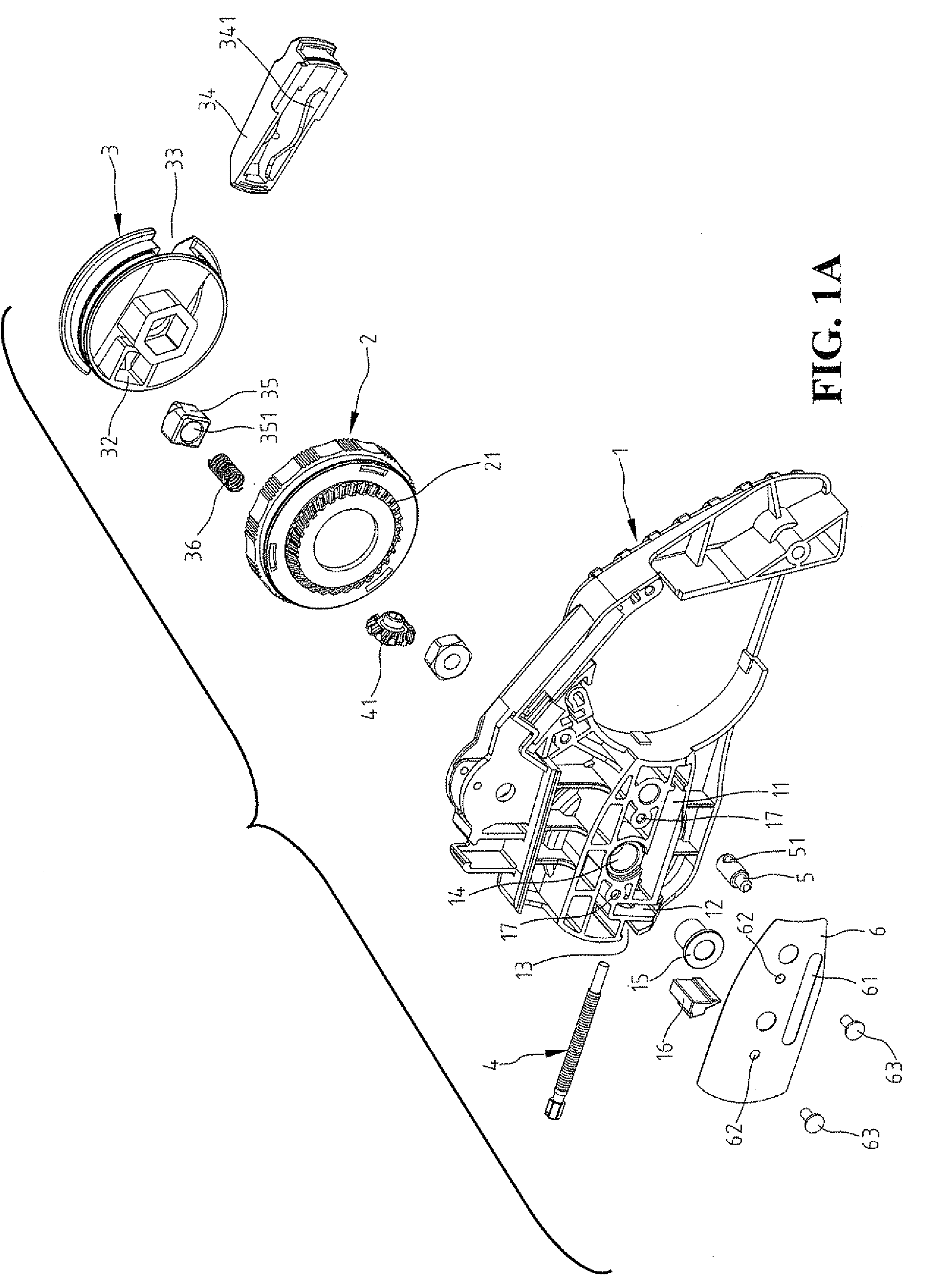
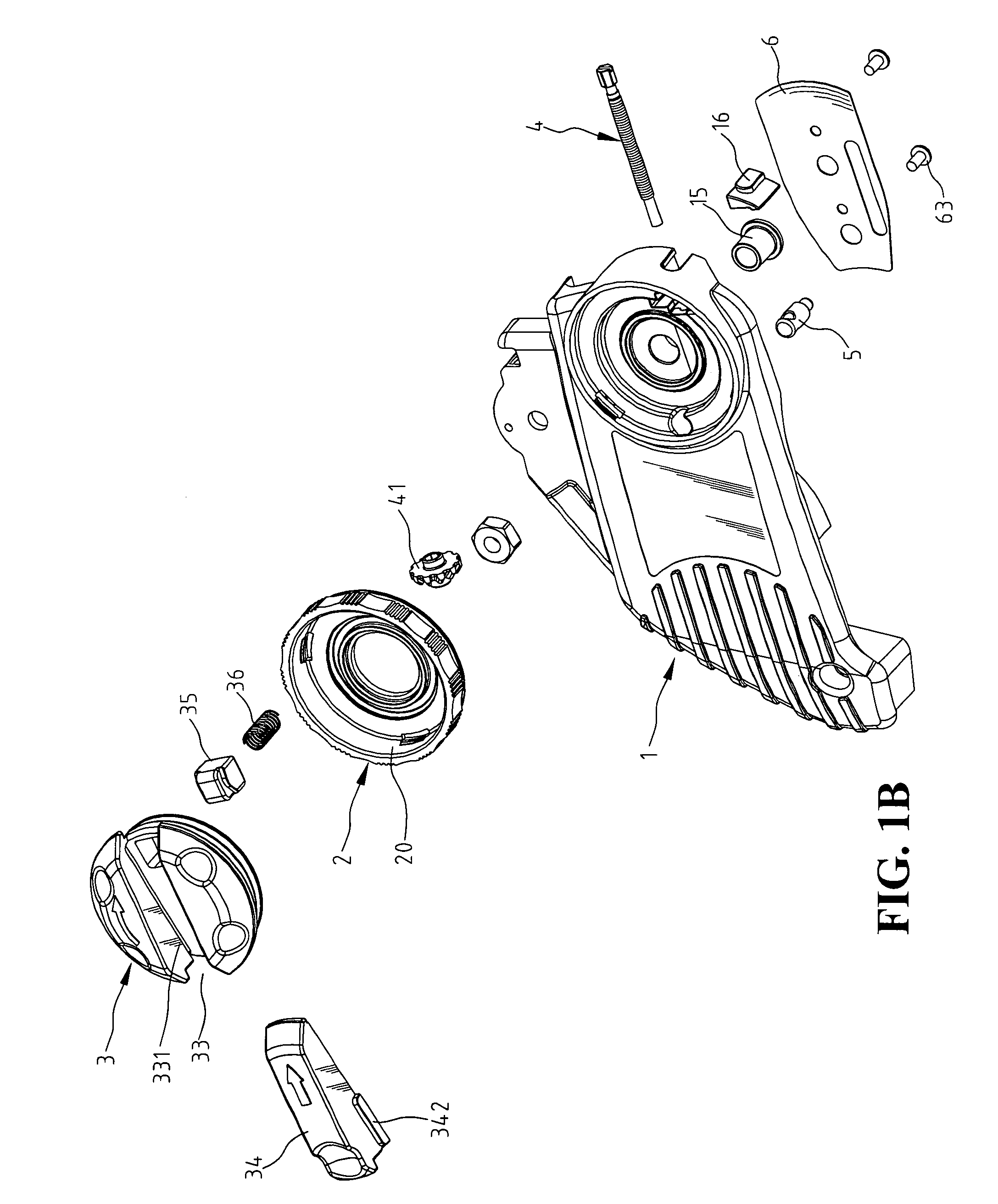
[0018]Referring to FIG. 1A and FIG. 1B, a keyless adjusting mechanism for a chain saw in accordance with a preferred embodiment of the present invention comprises a protection cover 1 having a first side and an opposite second side. A central hole 14 is formed from the first side to the second side of the protection cover 1 and has a bushing 15 received therein. The first side of the protection cover 1 has a first cover recess 11, a second cover recess 12, and a third cover recess 13 arranged in a line. The first cover recess 11 has a relatively longer length for receiving an adjusting bolt 4, which extends to the second recess 12. A driven gear 41 is coupled to an end of the adjusting bolt 4 and is received in the second cover recess 12. An elastic stopper 16 is received in the third cover recess 13 and is contacted with an end portion of the adjusting bolt 4 to prevent the adjusting bolt 4 from moving axially (see FIG. 3). In addition, an adjusting stud 5 used to connect a chain b...


PUM

PropertyMeasurementUnit
torqueaaaaaaaaaa
tensionaaaaaaaaaa
structureaaaaaaaaaa

Abstract

A keyless adjusting mechanism for a chain saw is disclosed herein, which comprises a protection cover, an adjusting bolt, an adjusting stud, and an adjusting ring with a driver gear, wherein the adjusting bolt is coupled with a driven gear for engaging with the driver gear of the adjusting ring, the adjusting stud is coupled with a chain board and has a threaded hole for engaging with the corresponding adjusting bolt. Accordingly, when the adjusting ring is rotated, the driver gear can bring the driven gear to let the adjusting stud move axially along the adjusting bolt such that the chain could be adjusted to tighten or loosen. In addition, a knob with a handle is coupled to the adjusting ring. The handle can be withdrawn in the knob or extended out of the knob for convenient twist.

Description

BACKGROUND OF THE INVENTION[0001]1. Field of the Invention[0002]The present invention generally relates to an adjusting mechanism for a chain saw that can adjust a tension of a chain without using auxiliary tools.[0003]2. The Prior Arts[0004]Taiwan application Nos. 90,213,097 and 94,211,435 both disclose an adjusting mechanism for adjusting a tension of a chain without using auxiliary tools. The conventional adjusting mechanism has a complicated structure, and has a knob that is inconvenient to twist.SUMMARY OF THE INVENTION[0005]An objective of the present invention is to provide an adjusting mechanism for a chain saw, which has simple structure and is laborsaving for adjusting a tension of a chain.[0006]Based on the above-mentioned objective, an adjust mechanism for a chain saw comprises a protection cover, an adjusting ring having a driver gear, an adjusting bolt having a driven gear for engaging with driver gear, and an adjusting stud. The adjusting stud is coupled with a chain ...

Claims


Application Information

Patent Timeline
Patent Type & Authority Patents(United States)
IPC IPC(8): B27B17/14
CPCB27B17/14Y10T83/7239
Inventor LIAO, CHIA-HSING
Owner HUSQVARNA AB
Why Eureka
Try Eureka