Gas leak detection apparatus

a technology of leak detection and gas, which is applied in the direction of instruments, fluid tightness measurement, operating means/release devices of valves, etc., and can solve problems such as danger to users

Inactive Publication Date: 2010-03-16
JIN BOR SHYH INDAL
View PDF4 Cites 4 Cited by
  • Summary
  • Abstract
  • Description
  • Claims
  • Application Information

AI Technical Summary

Benefits of technology

[0005]The primary objective of the present invention is to provide a gas leak detection apparatus, wherein if the pressure detector detects that the level of the control point of the pressure sensing device is changed during a preset period of time, which indicates that the gas leak happens to the pipe located at the rear side of the gas regulator, the pressure detector transmits the gas pressure signal from the

Problems solved by technology

However, gas leak easily happens to the pipe or the equipment located at the

Method used


Image

  • Gas leak detection apparatus
  • Gas leak detection apparatus
  • Gas leak detection apparatus

Examples


Embodiment Construction

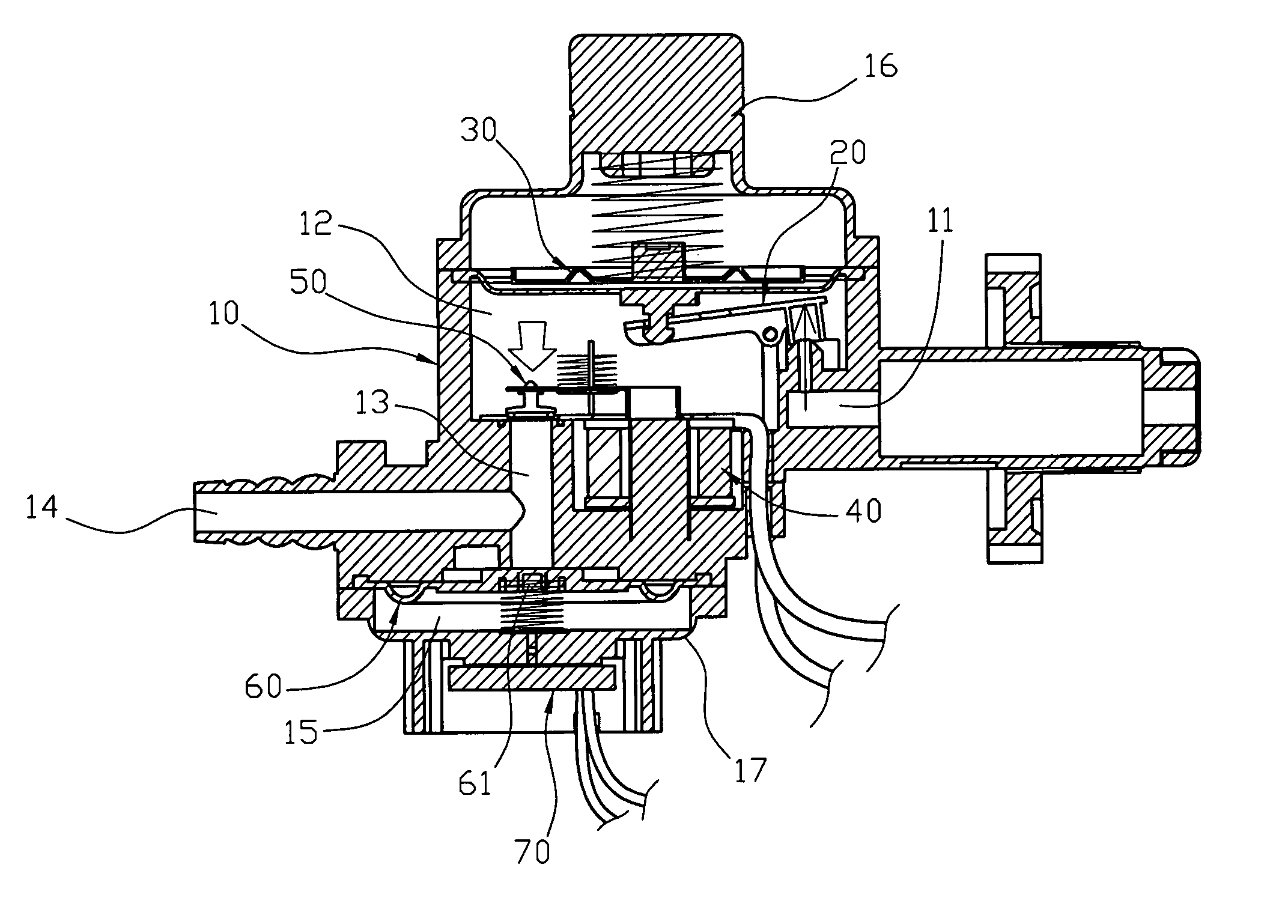
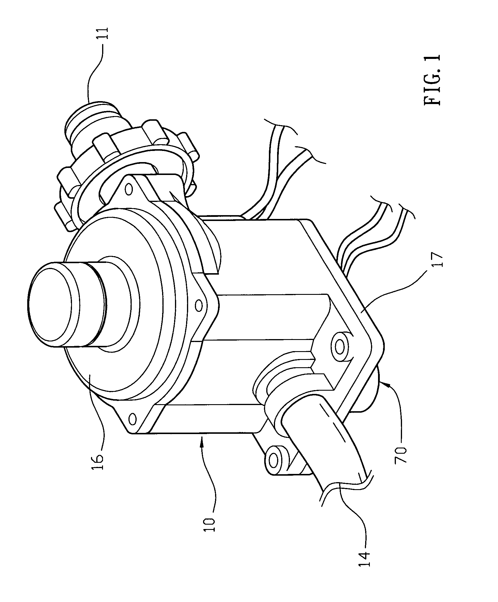
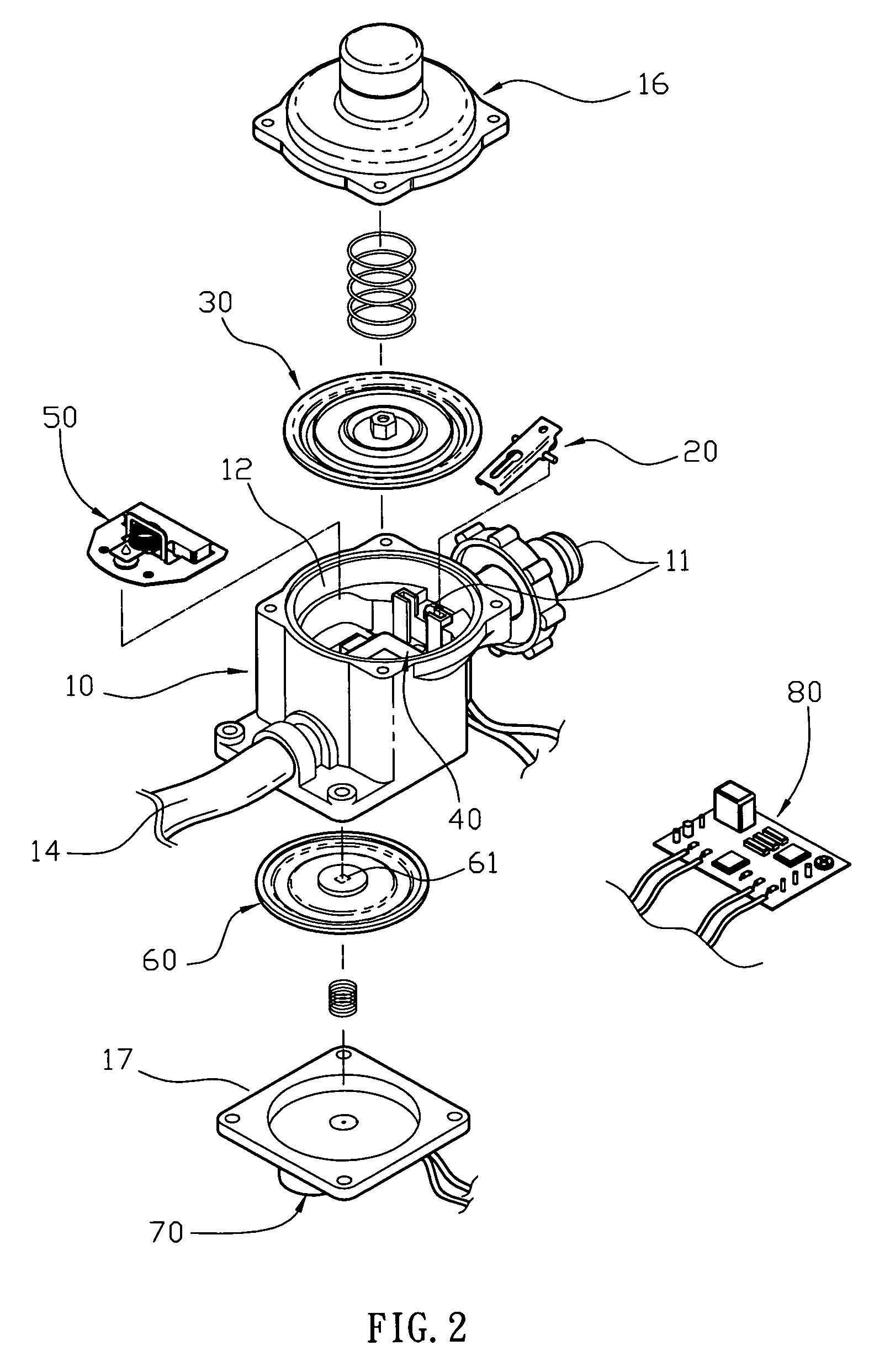
[0017]Referring to the drawings and initially to FIGS. 1-3, a gas leak detection apparatus in accordance with the preferred embodiment of the present invention comprises a main body 10 having a first side provided with an inlet 11 and a second side provided with an outlet 14 and having an inside formed with a detection chamber 15 (see FIG. 3) and a valve chamber 12 which has a first side connected to the inlet 11 and a second side provided with a conduit 13 connected to the outlet 14 and the detection chamber 15, a magnetically operated valve 50 mounted in the valve chamber 12 of the main body 10 to close or open the conduit 13 of the valve chamber 12, a magnetically exciting device 40 mounted in the valve chamber 12 of the main body 10 to control operation of the magnetically operated valve 50, a pressure sensing device 60 mounted in the detection chamber 15 of the main body 10 to sense a gas pressure contained in the conduit 13 of the valve chamber 12 to obtain a gas pressure sign...


PUM


Abstract

A gas leak detection apparatus includes a main body, a magnetically operated valve, a magnetically exciting device, a pressure sensing device, and a pressure detector. Thus, if the pressure detector detects that the gas leak happens to the pipe located at the rear side of the gas regulator, the control circuit board drives the magnetically exciting device to produce a magnetic force to drive the magnetically operated valve to close the conduit of the valve chamber and the outlet of the main body so as to interrupt the gas flow, thereby preventing the gas from entering the pipe located at the rear side of the gas regulator so as to provide a safety effect to the user.

Description

BACKGROUND OF THE INVENTION[0001]1. Field of the Invention[0002]The present invention relates to a detection apparatus and, more particularly, to a gas leak detection apparatus for a gas regulator.[0003]2. Description of the Related Art[0004]A conventional gas regulator is mounted on an outlet terminal or a dividing terminal of a pipe or an equipment to control the gas flow rate of the gas passing through the pipe or the equipment. However, gas leak easily happens to the pipe or the equipment located at the rear side of the gas regulator, thereby greatly causing danger to the user.BRIEF SUMMARY OF THE INVENTION[0005]The primary objective of the present invention is to provide a gas leak detection apparatus, wherein if the pressure detector detects that the level of the control point of the pressure sensing device is changed during a preset period of time, which indicates that the gas leak happens to the pipe located at the rear side of the gas regulator, the pressure detector transm...

Claims


Application Information

Patent Timeline
IPC IPC(8): G01M3/04
CPCF16K31/0682F16K31/402G01M3/2815F16K37/0041F16K37/005
Inventor LIN, YUNG-CHUN
Owner JIN BOR SHYH INDAL
Why Eureka
Try Eureka