Support bracket for a column

a support bracket and column technology, applied in the field of columns, can solve the problems of increasing construction costs, reducing construction efficiency, and reducing construction efficiency,

Inactive Publication Date: 2010-03-16
BAKOS STEPHEN M
View PDF7 Cites 61 Cited by
  • Summary
  • Abstract
  • Description
  • Claims
  • Application Information

AI Technical Summary

Benefits of technology

[0013]It is a further object of the present invention to provide a support bracket that reduces construction cost.
[0015]It is another object of the present invention to provide an integrated column and support bracket that provides vertical adjustment to position the column base at a desired elevation after installation at a construction site.

Problems solved by technology

Such repetitive use of the labor force, and the erection of temporary framework, is inefficient in time, energy, and / or materials, and increases construction costs.

Method used


Image

  • Support bracket for a column
  • Support bracket for a column
  • Support bracket for a column

Examples


Embodiment Construction

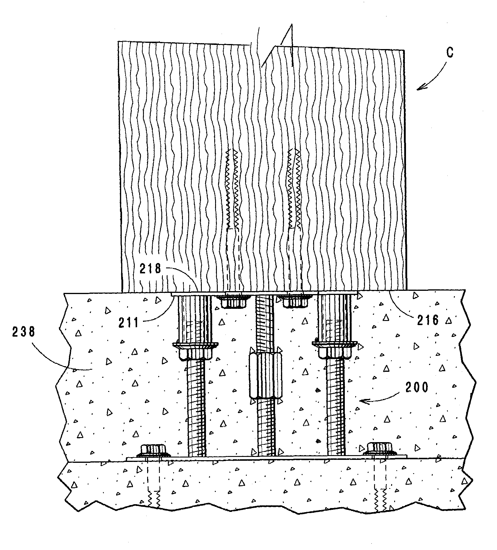
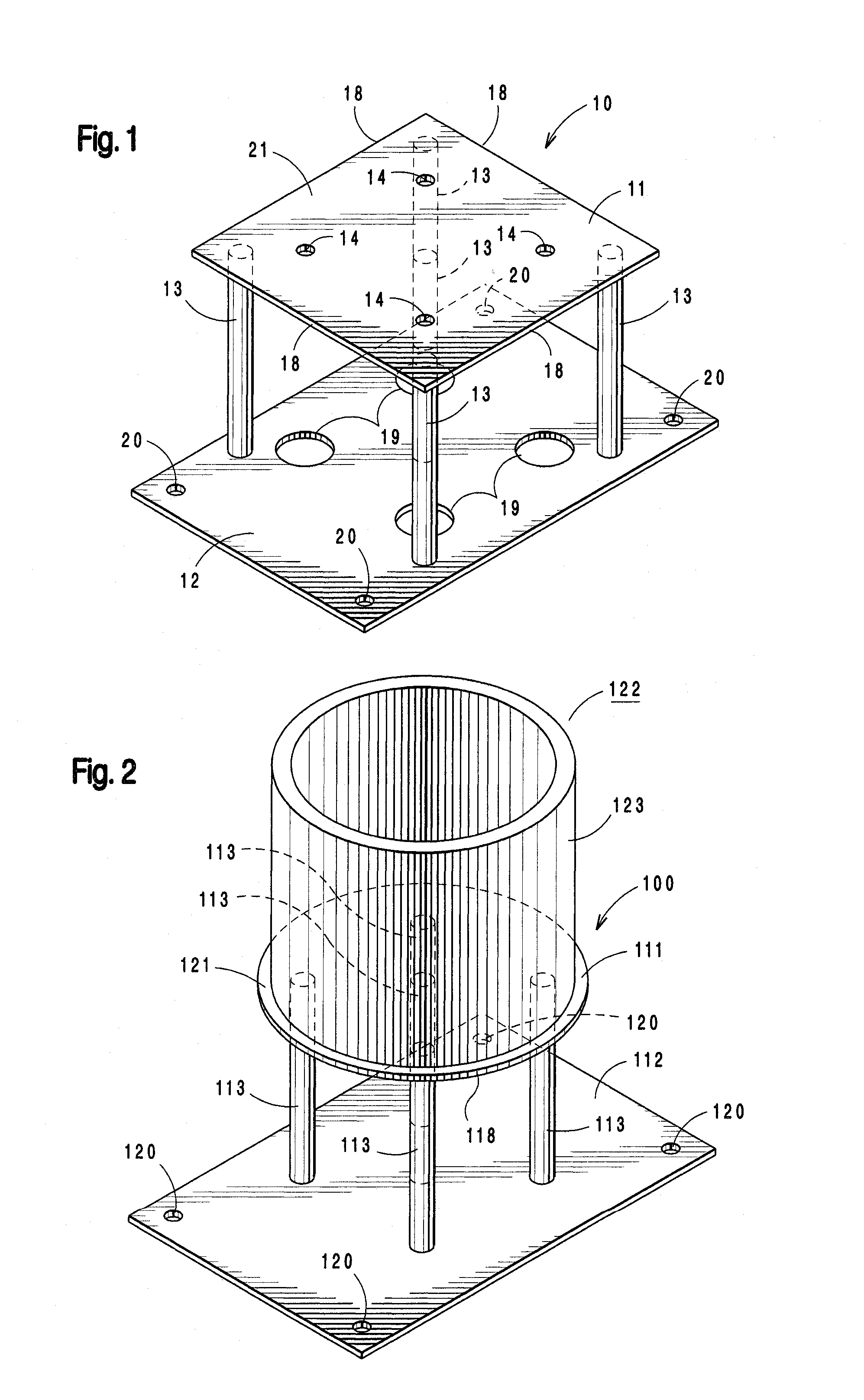
[0031]Referring to the drawings, FIG. 1 shows one embodiment of the present invention comprising a support bracket 10 that includes a top connection plate 11, a bottom foundation plate 12 and one or more struts 13 fixed to and extending between the connection plate and foundation plate. Connection plate 11 includes an arrangement of apertures 14 that accommodate fasteners 215 for fixing the connection plate to the underside surface or base 216 of column 217 (FIGS. 7-10). A set of apertures 19 in the foundation plate are aligned with apertures 14 in the connection plate to provide tool access for driving fasteners 215 into the base of column 17. Foundation plate 12 includes a second set of apertures 20 for attaching the foundation plate to a foundation using fasteners suited for the particular foundation installed at the jobsite.

[0032]The surface area 21 of the connection plate is less than the base surface area of column 217 so that the column overlaps the connection plate periphery...


PUM


Abstract

A, support bracket and column for supporting an elevated structure during and after construction. The support bracket includes a connection plate that is attached to and overlapped by the column base so that the support bracket is concealed from view when construction is completed, and variations of the support bracket provide means to raise or lower the attached column during construction.

Description

BACKGROUND[0001]The present invention is directed to a column support bracket that fixes a permanent column at a predetermined position during the construction phase of an elevated structure, an integrated column and support bracket where the bracket is concealed from view after construction of the elevated structure is completed.[0002]Architectural designs frequently include elevated structures, for example cantilevered decks, balconies, rooms, or the like that extend outward from the main building and require temporary support members during the construction phase. A footing or foundation wall is poured by concrete workers followed by carpenters who erect temporary bracing or framework to support the elevated structure during construction. When the structure is completed, the concrete workers and / or masons return to complete the foundation work which may include pouring a concrete slab, laying up masonry work or both. After the finish work is completed for the foundation, carpente...

Claims


Application Information

Patent Timeline
Patent Type & Authority Patents(United States)
IPC IPC(8): A47B97/00
CPCE02D27/42E04H12/2261
Inventor BAKOS, STEPHEN M.
Owner BAKOS STEPHEN M
Why Eureka
Try Eureka