Soldering or desoldering iron

a technology of desoldering iron and desoldering iron, which is applied in the direction of ohmic resistance heating, manufacturing tools, and sleeve b>53/b> to erode, and achieve the effect of minimizing the cost of replacement parts

Active Publication Date: 2010-03-16
HAKKO CO LTD
View PDF150 Cites 23 Cited by
  • Summary
  • Abstract
  • Description
  • Claims
  • Application Information

AI Technical Summary

Benefits of technology

[0006]This invention provides a soldering tool that includes a tip having a recess formed on its base. The temperature sensor may be provided on one end of a rod and the rod may be pressed through a thermal sleeve to allow at least a portion of the temperature sensor to protrude from the thermal sleeve. The recess in the tip is adapted to receive the protruding portion of the temperature sensor extending from the thermal sleeve. On the opposite end of the rod, electrical contacts may be provided to provide power to the heater mechanism embedded within the thermal sleeve. The electrical contact end of the heater mechanism is inserted into the handle and the tip is placed on top of the thermal sensor. A clamp is then placed over the tip and the sleeve, and is releasably engaged with the handle to securely hold the tip and the sleeve onto the handle. The tip is replaceable or separable from the thermal sleeve. This way, the tip alone may be replaced, for example when it becomes worn, rather than the entire thermal sleeve assembly, minimizing the cost of replacement parts.
[0007]The tip has a recess to receive the temperature sensor / heater combination protruding from the thermal sleeve. This allows the temperature sensor / heater combination to be closer to the tip so that the tip may be heated to the desired temperature more quickly and the temperature of the tip monitored more accurately. The sensor can extend between the tip and the sleeve to monitor the temperature of both the tip and the sleeve. This allows the sensor to measure the average temperature between the tip and the sleeve. In addition, the sensors are placed near the outer surface of the ceramic heater to better monitor the temperature of the tip and the sleeve. The temperature sensor and the heater may be bonded together so that they are thermally unified whereby the tip, sensor, and the heater will all have substantially the same temperature during the operation of the soldering tool.

Problems solved by technology

This gap inhibits thermal heat from conducting from the heater 52 to the sleeve 53, resulting in poor thermal efficiency.
After a period of use, oxidization may form near the gap due to high temperature around the gap.
This in turn may cause the sleeve 53 to erode due to oxidization.
The oxidization in the gap further reduces the thermal efficiency of the soldering iron 50.
To compensate for the delay, the conventional soldering irons use expensive control devices, such as proportional, integral, derivative (PID) devices, to control the temperature of the tip.
The delay also makes the conventional soldering iron inefficient because when the conventional soldering iron is initially turned on, the heater generates excess heat above the desired set temperature value.
That is, the control device continues to provide power to the heater because the temperature sensor is slow to measure the rise in temperature near the tip.

Method used


Image

  • Soldering or desoldering iron
  • Soldering or desoldering iron
  • Soldering or desoldering iron

Examples


Embodiment Construction

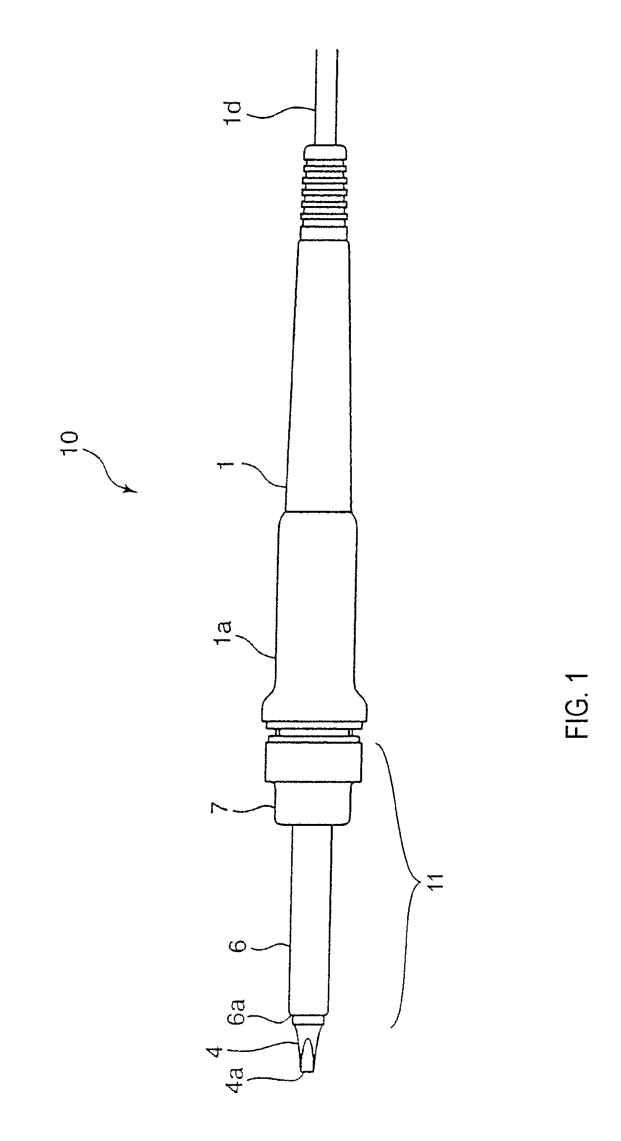
[0049]FIG. 1 illustrates a soldering iron generally at 10 having a heater cartridge assembly 11 and a removable and replaceable tip 4 protruding from the assembly. The tip 4 may be replaced with another tip as the tip wears out or when a different tip is better suited for a particular soldering operation. The soldering iron 10 includes a clamping ring or member 7 that releasably holds the heater cartridge assembly 11 to the casing 1. As further discussed below, the heater cartridge assembly 11 includes a locking tube 6 that retains the tip 4 such that the tip protrudes from the locking tube. To replace the tip 4, the clamping ring 7 may be disengaged from the casing 1 to release the heater cartridge assembly 11 from the casing, and the tip 4 may then be released from the heater cartridge assembly 11 and replaced with another desired tip.

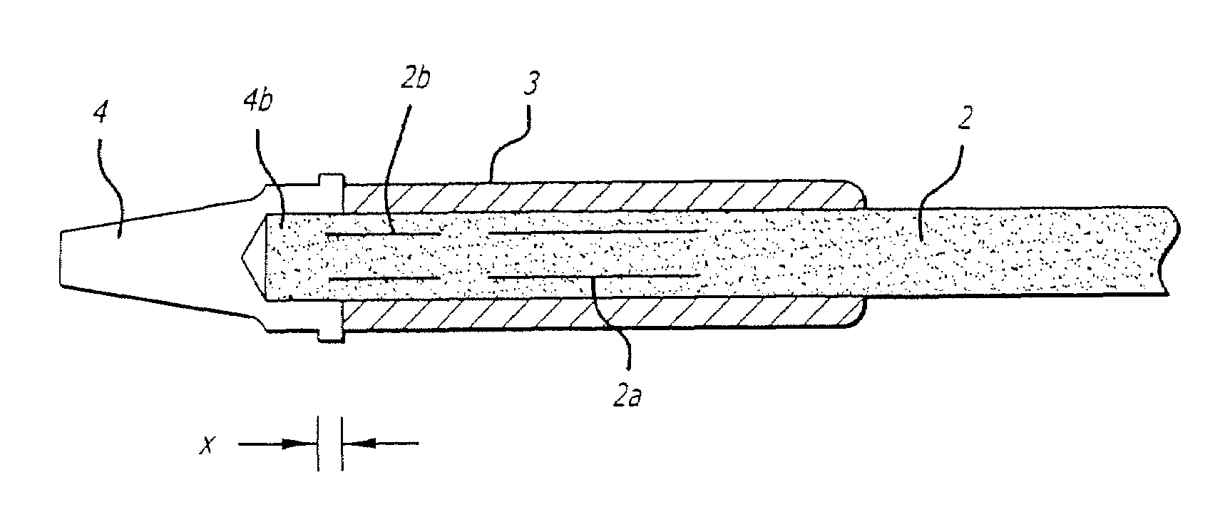
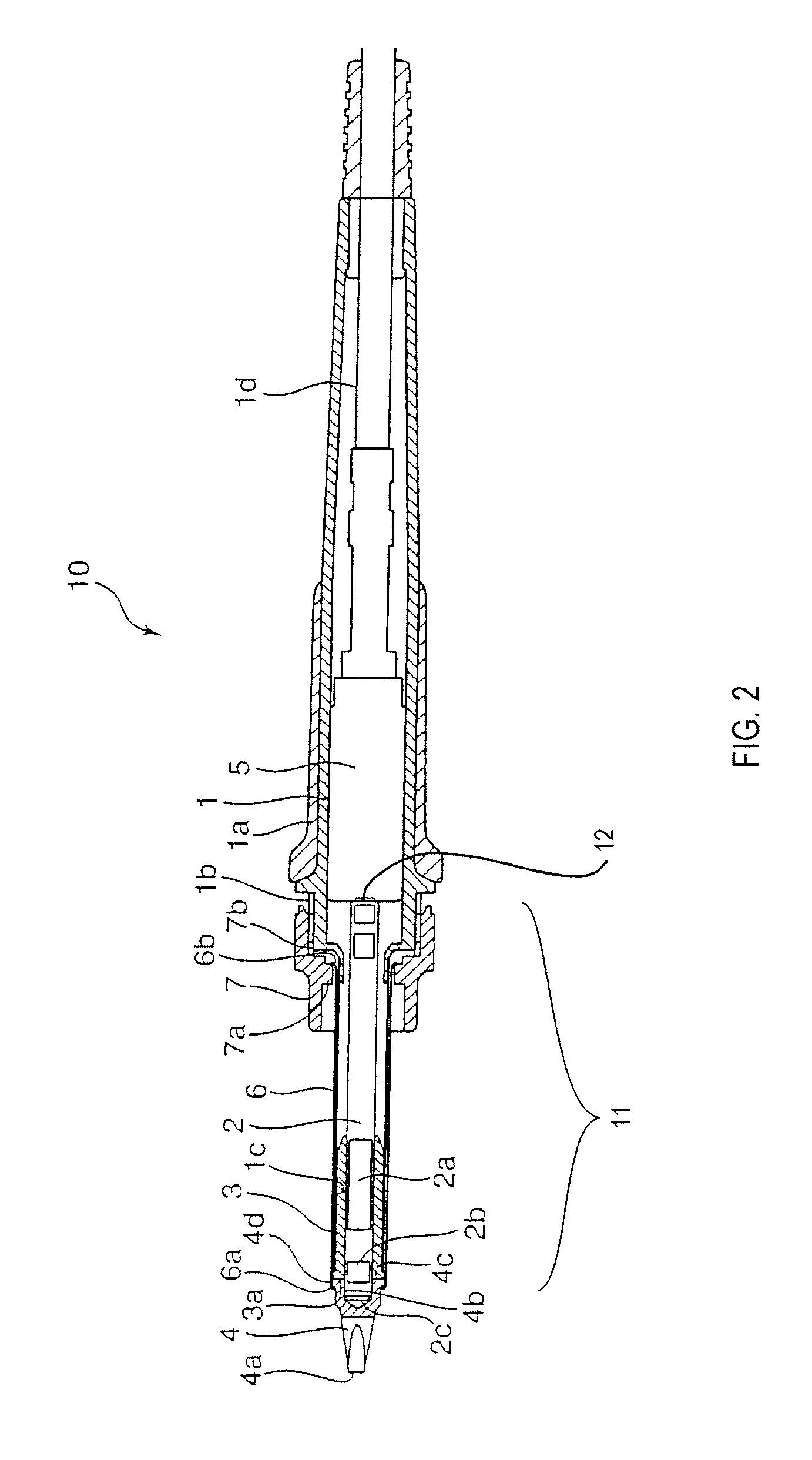
[0050]FIG. 2 is a cross-sectional view of the soldering iron 10, and FIG. 3 is a close up view of the heater cartridge assembly area. The heater car...


PUM

PropertyMeasurementUnit
thicknessaaaaaaaaaa
depthaaaaaaaaaa
depthaaaaaaaaaa

Abstract

A soldering or a desoldering tool includes a replaceable tip with a recess adapted to receive a portion of a temperature sensor to measure the temperature of the tip. Positioning the temperature sensor within the tip allows the temperature to be quickly measured so that the temperature near the tip may be more accurately monitored and controlled. The temperature sensor may be also integrated with the heater near the tip such that the temperature sensor is between the tip and the heater and near both of them so that the temperature of the tip is substantially that of the temperature of the heater. A sleeve may enclose the temperature sensor and the heater with a portion of the temperature sensor extending out from the foreward end of the sleeve. The replaceable tip may also have a bore adapted to receive a head protruding from the foreward end of the sleeve to couple the tip at a predetermined orientation with respect to the sleeve. The combination of bore and head allows the replaceable tip to be coupled with the sleeve in a consistent manner so that the temperature of the replacement tips can be measured accurately and dependably.

Description

CROSS-REFERENCE TO RELATED APPLICATION[0001]This application claims priority to Japanese Patent Application No. JP-App-2003-191852, filed Jul. 4, 2003, which is hereby incorporated by reference.FIELD OF THE INVENTION[0002]This invention relates to a soldering iron or a desoldering iron, and in particular to a soldering (or desoldering) iron capable of accurately measuring the temperature of its tip and of having its tip replaced if needed.BACKGROUND OF THE INVENTION[0003]FIG. 11 is a cross-sectional view of a conventional soldering iron 50 in a disassembled state. The conventional soldering iron 50 has an insert pipe 51 for coupling a heater 52 to a sleeve 53 which has a protruding tip 54. The heater 52 is removeably inserted into the sleeve 53 so that heat from the heater is conducted to the tip 54. The insert pipe 51 is positioned between the sleeve 53 and the heater 52; when in position a gap is formed between the sleeve 53 and the heater 52. This gap inhibits thermal heat from c...

Claims


Application Information

Patent Timeline
Patent Type & Authority Patents(United States)
IPC IPC(8): H05B3/42B23K3/02H05B3/16B23K3/04B23K3/03
CPCB23K3/033B23K3/0353B23K3/0369B23K3/04B23K3/027
Inventor MASAKI, HIROYUKI
Owner HAKKO CO LTD
Why Eureka
Try Eureka