System and method for optical photomask inspection through pellicle

Inactive Publication Date: 2010-03-16
N & K TECH
View PDF11 Cites 0 Cited by
  • Summary
  • Abstract
  • Description
  • Claims
  • Application Information

AI Technical Summary

Benefits of technology

[0009]A system for photomask inspection through a pellicle on top and eventually on bottom of the photomask includes an optical n&k analyzer commercially available from n&k Technology™, a pellicle correction factor lookup table and a computing subsystem for computationally accessing the pellicle correction factor lookup table such that operational photomask measurements through the pellicle(s) may be computationally corrected for pellicle related optical distortions. In the pellicle correction factor lookup table may be stored pellicle correction factors that are computed from a first baseline measurement of a reference photomask without pellicle and from a second baseline measurement of the reference photomask with a reference type pellicle on the reference photomask. Pellicle correction factors m

Problems solved by technology

This may be particularly an issue with thin pellicles 6 commonly made of organic plastic material with thickness of about less than 10 micron, which are commonly employed with photomasks 1 operated during semiconductor fabrication in conjunction with light sources in the visual spectrum.
Such materials are commonly very brittle and are made with thickness of 100 microns up to about to 200 microns.
Moreover and due to fabrication cost limitations, the inorganic pellicle 6 may be of limited optical quality with fabrication inconsistencies across its surface area that may introduce localized distortion characteristics.
Common photomask inspection devices have the optics very close to the photomask making unimpeded photomask inspection through the pellicle 6 difficult if not impossible to accomplish.

Method used


Image

  • System and method for optical photomask inspection through pellicle
  • System and method for optical photomask inspection through pellicle
  • System and method for optical photomask inspection through pellicle

Examples


second embodiment

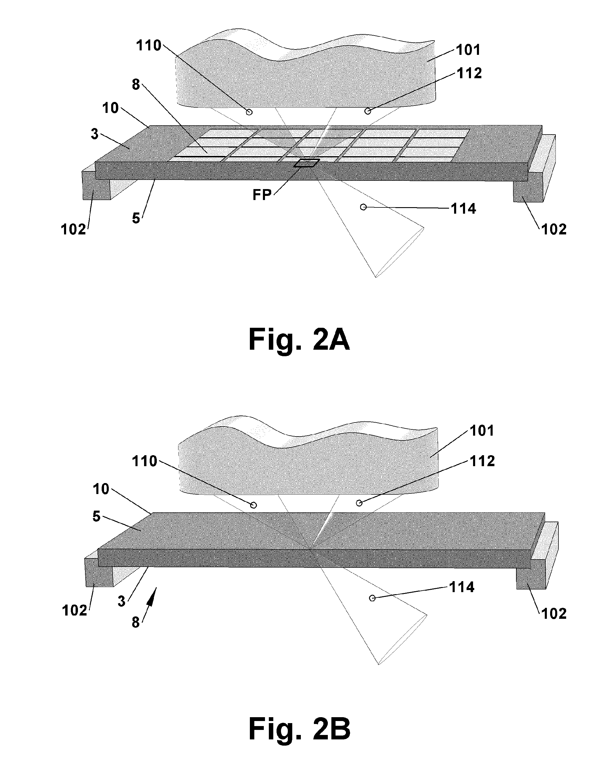
[0021]Referring to FIG. 2A, a particular feature of the n&k analyzer 101 is an extended clearance height between its optical head and the well known focal plane FP within which the emitted light beam 110 is focused. The extended clearance may be more than the conventional pellicle 6 height. The focal plane FP of the photomask analyzer 101 may consequently be moved onto the mask 8 top layer without the optical head colliding with the pellicle 6 or pellicle frame 4. Moreover, the optical head may be kept in a clearance above the pellicle 6 such that sufficient clearance is provided above a thin pellicle 6 that eventually bulges due to internal pressure rise in the sealed volume between the pellicle 6, the pellicle frame 4 and a reference photomask 10 or a generic photomask 1. In addition, the n&k analyzer 101 features a vertical travel range at least equal to the conventional pellicle 6 height for moving the focal plane FP on the pellicle 6 itself. In that way, identification of the p...

first embodiment

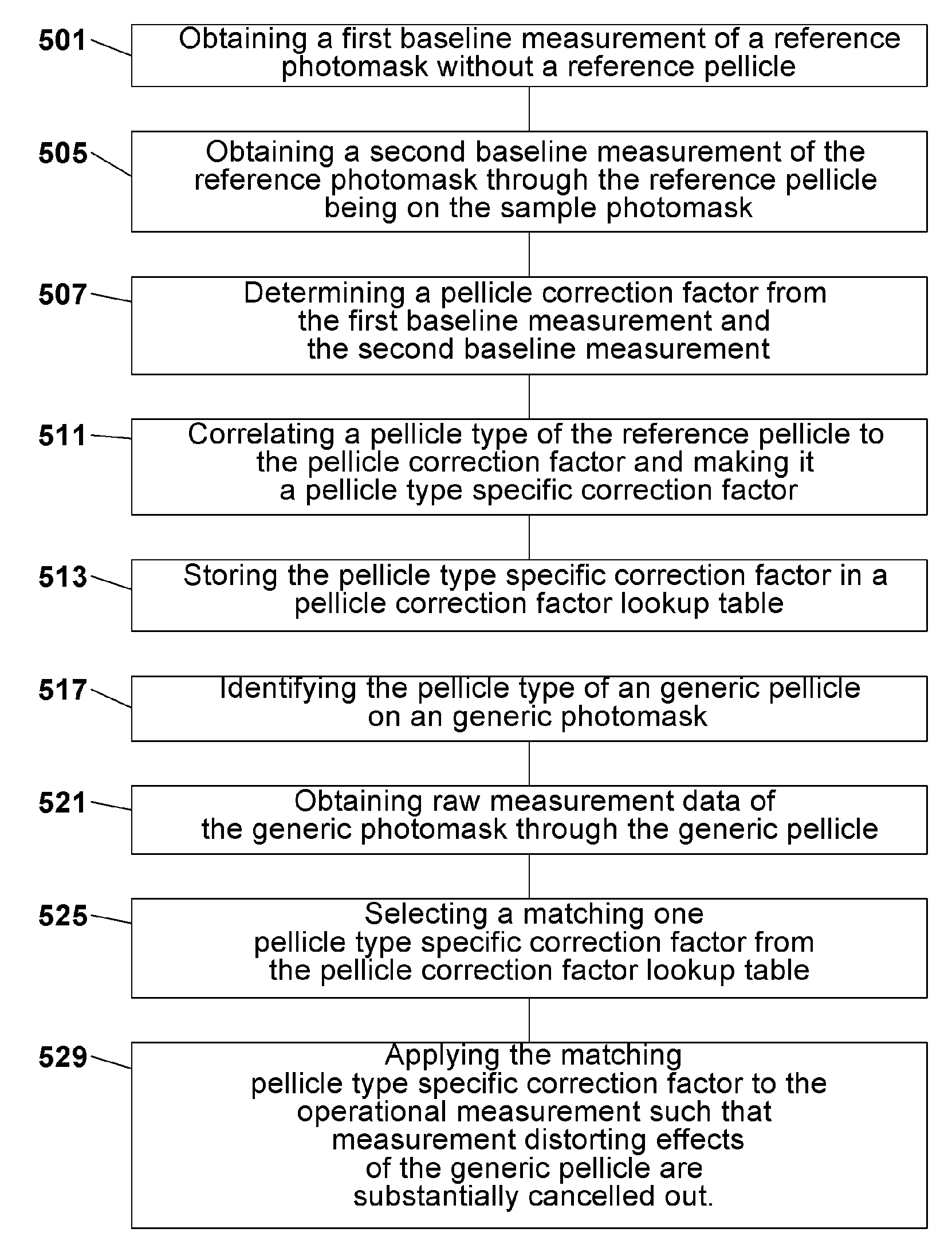
[0022]Referring to FIGS. 2A-3B and 5, the invention is preferably employed in conjunction with highly type homogeneous pellicles 6 such as thin pellicles 6. Type homogenous in context with the present invention means that by examining a defined number of reference pellicles 6 of the same type, pellicle 6 information may be obtained for its optical distortion characteristics including reflectance and transmittance attenuation properties that may be applied in form of a pellicle type specific correction factor 143 for other pellicles 6 of that same type. As a result, by testing a representative number of reference pellicles 6 of a particular type such as a well known 193′ pellicle or 248′ pellicle for 193 nm wavelength light or 248 nm wavelength light respectively, pellicle type specific correction factors 143 for reflectance and transmittance may be calculated and applied to all consecutive generic photomask 1 measurements through a number of generic pellicle types the matching pelli...


PUM


Abstract

A pellicle correction factor is determined by comparing a first measurement of a reference photomask alone with a second measurement of that reference photomask through a reference pellicle protecting the mask layers of the photomask. A number of pellicle correction factors may be determined for different type pellicles and made accessible in pellicle correction factor lookup table of the system or supplied on a separate data storage medium. Raw Reflectance and / or Transmittance measurement data of a generic photomask through a generic pellicle is consecutively corrected for the measurement distorting effects of that pellicle by applying a matching one of the previously determined pellicle correction factors. The pellicle correction factor is preferably an attenuation signature across a predetermined measurement irradiation spectrum.

Description

PRIORITY CLAIM[0001]The present application claims priority to and from Provisional Patent Application titled “Photomask Measurement Through Pellicle” of the same inventors, Application No. 60 / 952,549, filed Jul. 27, 2007.CROSS REFERENCE[0002]The present invention cross references the US Patent Application of the same inventors titled “Automated Spatial Flipping Apparatus And System For Photomasks And Photomasks With Pellicles”, application Ser. No. 12 / 050,387, filed Mar. 18, 2008, which is hereby incorporated by reference.FIELD OF INVENTION[0003]The present invention relates to systems and methods for photomask measurements through a pellicle on a measured photomask. In particular, the present invention relates to systems and methods for photomask measurements through a pellicle on a measured photomask by applying a previously determined pellicle correction factor.BACKGROUND OF INVENTION[0004]Referring to Prior Art FIGS. 1A, 1B, suppliers of photomasks 1 commonly apply a thin pelli...

Claims


Application Information

Patent Timeline
IPC IPC(8): G01N21/00
CPCG01N21/956G01N2021/95676
Inventor AHO, MARC T.WILSON, THADDEUS J.ROBERTS, JEFF
Owner N & K TECH
Why Eureka
Try Eureka