Optical tracking system for refueling

a tracking system and optical technology, applied in the direction of beacon systems using electromagnetic waves, instruments, measurement devices, etc., can solve the problem of difficult positioning of the refueling probe of the aircraft to be refueled in the refueling drogu

Active Publication Date: 2010-03-23
SMITHS AEROSPACE INC
View PDF90 Cites 50 Cited by
  • Summary
  • Abstract
  • Description
  • Claims
  • Application Information

AI Technical Summary

Problems solved by technology

Unfortunately, the hose-drogue combination has a relatively large dynamic response to disturbances, so when the drogue is subjected to wind gusts and / or turbulence, the hose-drogue combination moves relative to the refueling aircraft, as forces imparted onto the drogue by the air cause the drogue to move.
These phenomenon make it difficult to position the refueling probe of the aircraft to be refueled in the refueling drogue.

Method used


Image

  • Optical tracking system for refueling
  • Optical tracking system for refueling
  • Optical tracking system for refueling

Examples


Embodiment Construction

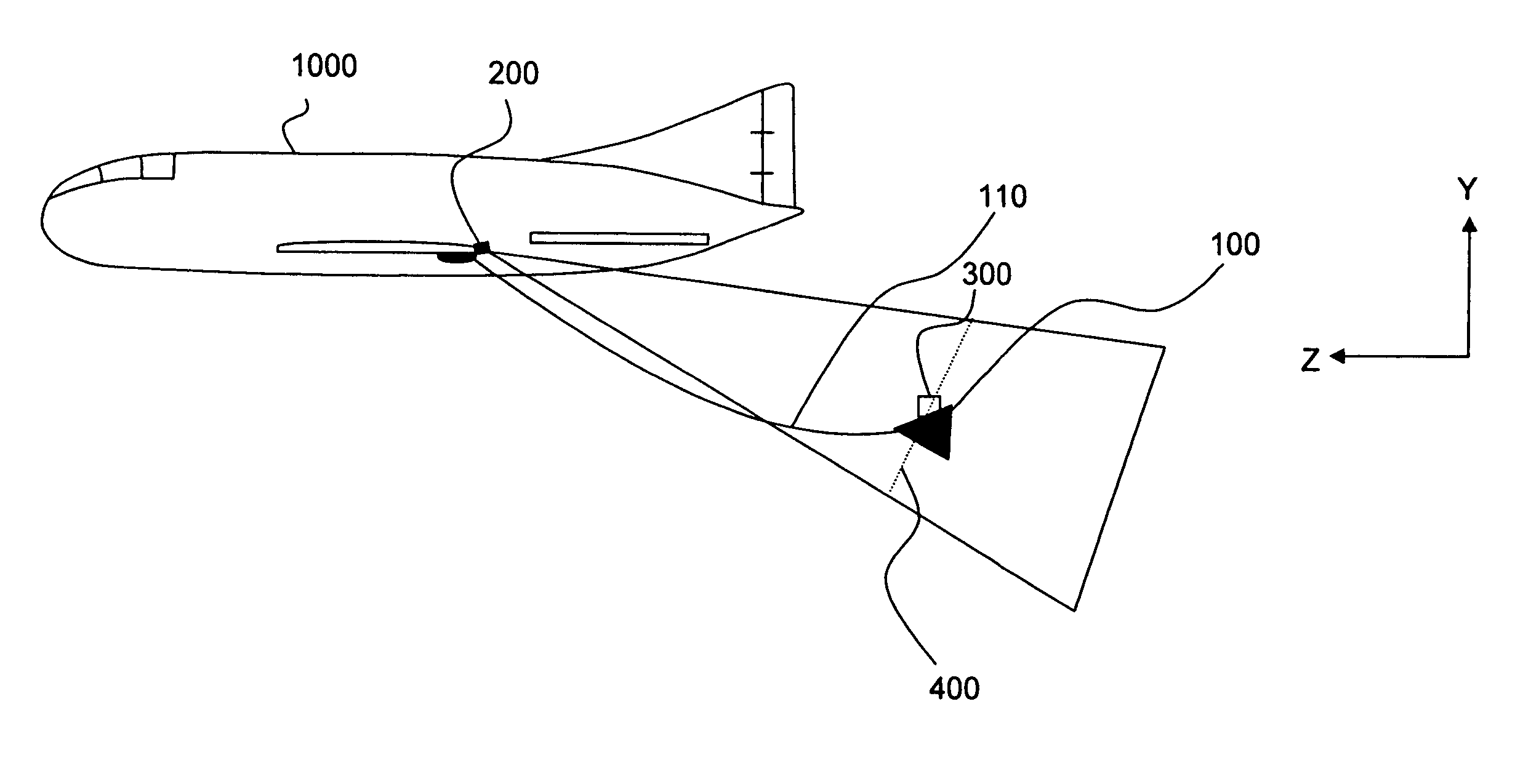
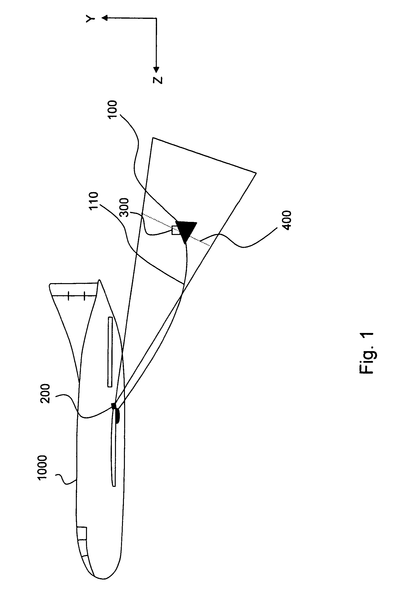
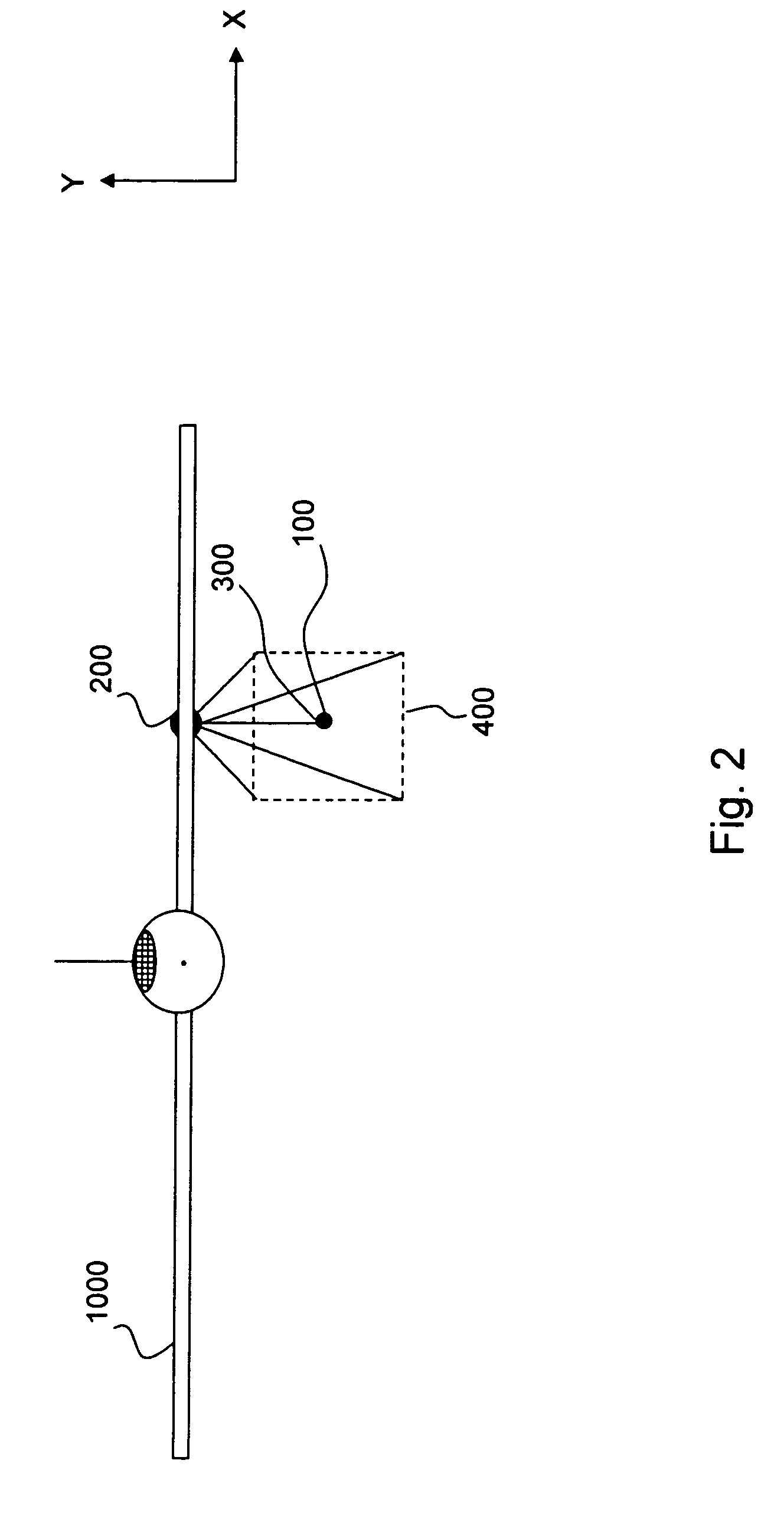
[0035]The present invention is directed towards systems, methods and apparatuses for enabling a drogue in general and a refueling drogue in particular to determine its position relative to a fixed referenced point on the aircraft to which the drogue is coupled (e.g., refueling aircraft). Moreover, the present invention is directed towards systems, methods and apparatuses for enabling a drogue in general and a refueling drogue in particular to substantially maintain a position relative to the fixed reference point (also known as station keeping) based on this determined position. In exemplary embodiment, this fixed reference point is a radiation emitter on the wing of the refueling aircraft, as will be discussed below. An exemplary embodiment of the present invention, coupled with exemplary scenarios utilizing the present invention, will now be described followed by detailed discussions of particular embodiments of the present invention.

[0036]In a first embodiment of the present inve...


PUM


Abstract

An aerial refueling system including a refueling drogue assembly including a refueling drogue and a refueling hose in captive relation with the refueling drogue and a drogue positioning system. The drogue positioning system including a radiation emitter, a radiation receiver and a signal processor. Then the radiation emitter is adapted to direct radiation to a positioning area a defined distance from the radiation emitter, the radiation carrying a modulated location signal containing information corresponding to positions within the positioning area. The radiation receiver is adapted to receive at least a portion of the emitted radiation carrying the modulated signal and output a signal to the signal processor indicative of the modulation of the location signal of the received radiation. And the signal processor is adapted to process the outputted signal and identify a position within the positioning area indicative of the location in the positioning area of the received radiation.

Description

CROSS-REFERENCE TO RELATED PATENT APPLICATIONS[0001]This patent application claims priority to U.S. Provisional Patent Application Ser. No. 60 / 656,084, entitled Optical Tracking System for Refueling, filed on Feb. 25, 2005, the contents of which are incorporated herein by reference in its entirety.BACKGROUND OF THE INVENTION[0002]Aerial refueling via the probe and drogue method is known. In an exemplary refueling scenario, a refueling drogue connected to a refueling hose is unreeled from a refueling aircraft (e.g., tanker aircraft) towards a receiver aircraft (an aircraft to be refueled), such as a fighter plane, a helicopter, etc. The receiver aircraft has a refueling probe extending from the aircraft. The receiver aircraft maneuvers to the refueling drogue and inserts its refueling probe into the refueling drogue, at which point the refueling drogue “locks” onto the refueling probe, and a transfer of fuel from the refueling aircraft to the receiver aircraft is conducted.[0003]It i...

Claims


Application Information

Patent Timeline
Patent Type & Authority Patents(United States)
IPC IPC(8): B64D39/00G01B11/14
CPCG01S1/70B64D39/00B64D39/06
Inventor MICKLEY, JOSEPH G.STITT, RAYMOND MICHAELSAGGIO, III, FRANKPAVLICH, JANE C.WASSICK, GREGORY J.
Owner SMITHS AEROSPACE INC
Why Eureka
Try Eureka