Ambiguity-free optical tracking system

a tracking system and optical tracking technology, applied in the field of radiotherapy, can solve the problems of difficult to decide if the patient displacement is within the tolerance margin, the majority of the time the patient is not suitable for real-time and continuous monitoring during treatment, and the risk of excessive radiation exposure to the patien

Inactive Publication Date: 2015-03-26
UNIV OF FLORIDA RES FOUNDATION INC
View PDF4 Cites 51 Cited by
  • Summary
  • Abstract
  • Description
  • Claims
  • Application Information

AI Technical Summary

Benefits of technology

[0016]In another embodiment, a method of corresponding a set of reference markers [Ai] from a CT scan to a set of optical markers [Bj] detected by cameras in a radiation treatment room is disclosed. The method comprises placing retro-reflective markers on a patient; performing a CT scan of the patient and the retro-reflective markers; assigning x, y, z coordinates to each reference marker of a set of reference markers that appears in the CT scan; determining a distance between each reference markers and each of the other reference markers; viewing the patient and the retro-reflective markers, with cameras in a radiation treatment room; assigning x, y, z coordinates to each optical marker of a set of optical markers created as a result of the viewing; determining a distance between each optical mark

Problems solved by technology

Without accurate and continuous monitoring of the patient, it is difficult to decide if the patient displacement is within the tolerance margin.
Known x-ray based image guidance systems provide adequate accuracy for initial patient positioning, but most of them are not appropriate for real-time and continuous monitoring during the treatment.
But continuous fluoroscopy during long treatment durations is associated with the risk of excessive radiation exposure to the patient.
However, CBCT is limited to an angle of a treatment couch of 0° and CBCT cannot acquire images in real-time.
As a result, a time consuming trial and error process must then be used to remove one of the two true markers that caused the ambiguous marker.
Additionally, a reduction in number of true markers for any reason, including the removal of a true marker to eliminate the ambiguous marker, degrades accuracy.
However, the second known system suffers from the ambiguous markers problem and

Method used


Image

  • Ambiguity-free optical tracking system
  • Ambiguity-free optical tracking system
  • Ambiguity-free optical tracking system

Examples


Embodiment Construction

[0029]As required, detailed embodiments of the present invention are disclosed herein. However, it is to be understood that the disclosed embodiments are merely examples of the invention, which can be embodied in various forms. Therefore, specific structural and functional details disclosed herein are not to be interpreted as limiting, but merely as a basis for the claims and as a representative basis for teaching one skilled in the art to variously employ the present invention in any appropriately detailed structure and function. Furthermore, the terms and phrases used herein are not intended to be limiting; but rather, to provide an understandable description of the invention.

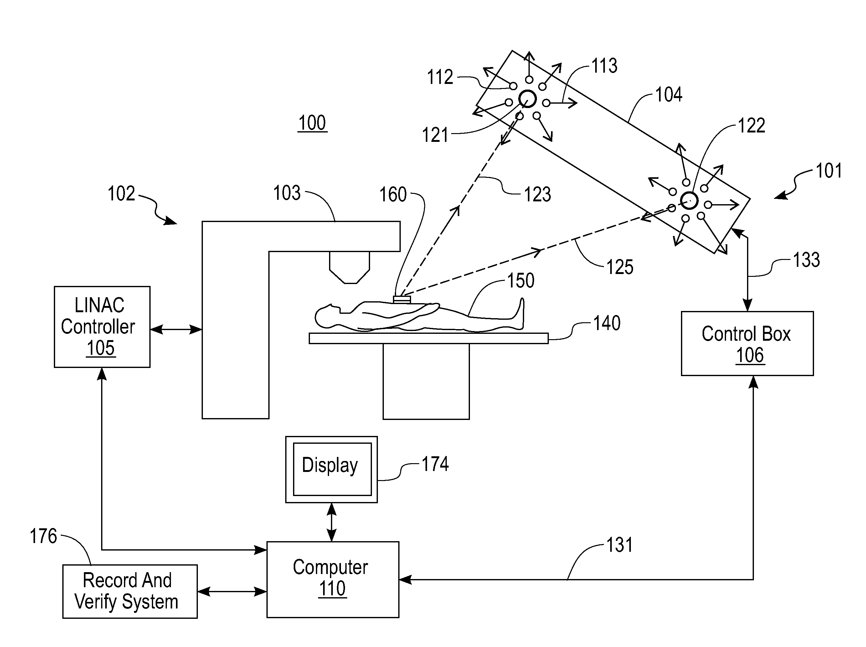
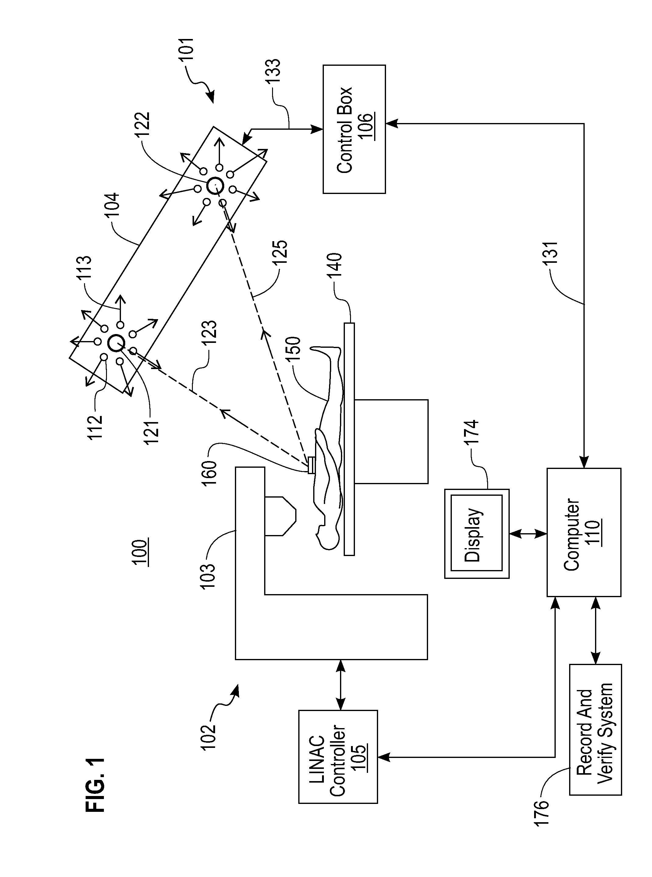
[0030]FIG. 1 is a simplified block diagram of one embodiment of an ambiguity-free optical tracking system 101 in accordance with the invention, and a radiation delivery system 102. The ambiguity-free optical tracking system 101 is ambiguity-free because it automatically identifies and eliminates ambiguous mar...


PUM


Abstract

An ambiguity-free optical tracking system (100) includes a position sensor unit (104), a control box (106), a computer (110) and software. The position sensor unit includes two cameras (121 and 122) that track a plurality of individual infra-red reflecting markers (160) affixed on a patient's skin. Coordinates of the cameras in a coordinate system of the cameras are determined as part of a system calibration process by intentionally creating ambiguous markers with two true markers. Using this information, an ambiguity elimination algorithm automatically identifies and eliminates ambiguous markers. A recursive backtracking algorithm builds a one-to-one correspondence between reference markers and markers optically observed during treatment. By utilizing a concept of null markers, the backtracking algorithm deals with missing, misplaced and occluded markers.

Description

CROSS-REFERENCE TO RELATED APPLICATIONS[0001]This application is based upon and claims priority to U.S. Provisional Patent Application Serial No. 61 / 623,395, entitled “DEVELOPMENT AND EVALUATION OF AN AMBIGUITY-FREE TRACKING SYSTEM FOR EXPANDED USE IN RADIOTHERAPY”, filed Apr. 12, 2012, the disclosure of which is hereby incorporated by reference in its entirety.STATEMENT REGARDING FEDERALLY SPONSORED RESEARCH[0002]None.FIELD OF THE INVENTION[0003]The present invention generally relates to the field of radiotherapy, and more particularly to optical tracking systems.BACKGROUND OF THE INVENTION[0004]In targeted radiation therapy such as intensity-modulated radiation therapy (IMRT) and stereotactic body radiation therapy (SBRT), it is critical to position a patient in a treatment position accurately and reproducibly. It is also highly desirable to have accurate and continuous localization of the patient throughout radiation delivery, especially for a patient having lesions in thoracic a...

Claims


Application Information

Patent Timeline
IPC IPC(8): H04N13/00G01B11/25G01S17/87
CPCG01B11/254H04N13/0048A61B6/03G01S17/48G01S17/66G01S17/87A61N5/1049A61N2005/1059A61B6/583H04N13/161A61N5/1048A61N5/107A61N2005/1051A61N2005/1074
Inventor YAN, GUANGHUALU, BOLIU, CHIHRAYLI, JONATHAN G.
Owner UNIV OF FLORIDA RES FOUNDATION INC
Why Eureka
Try Eureka