Digital distributed antenna system

a distributed antenna and digital technology, applied in the field of wireless communication systems and methods, can solve the problems of either too large or too expensive a solution for base stations

Active Publication Date: 2009-07-16
INTEL CORP
View PDF45 Cites 198 Cited by
  • Summary
  • Abstract
  • Description
  • Claims
  • Application Information

AI Technical Summary

Benefits of technology

[0017]The digital distributed wireless communication system further includes a Control & Management (C&M) processor for processing C&M data plane provided to the plurality of remote transceiver units. The digital distributed interface unit provides control comma

Problems solved by technology

An example is in-building coverage where low cost radiating antennas are desired and base stations represent either too large or too expensive a solution.
With this, a wireless coverage system incorporating

Method used


Image

  • Digital distributed antenna system
  • Digital distributed antenna system
  • Digital distributed antenna system

Examples


Embodiment Construction

[0029]The invention provides an improved base station system and method of simulcasting a digital multiplexed signal to and from multiple digital radio heads with the necessary synchronization and control aspects to eliminate time delay ambiguities.

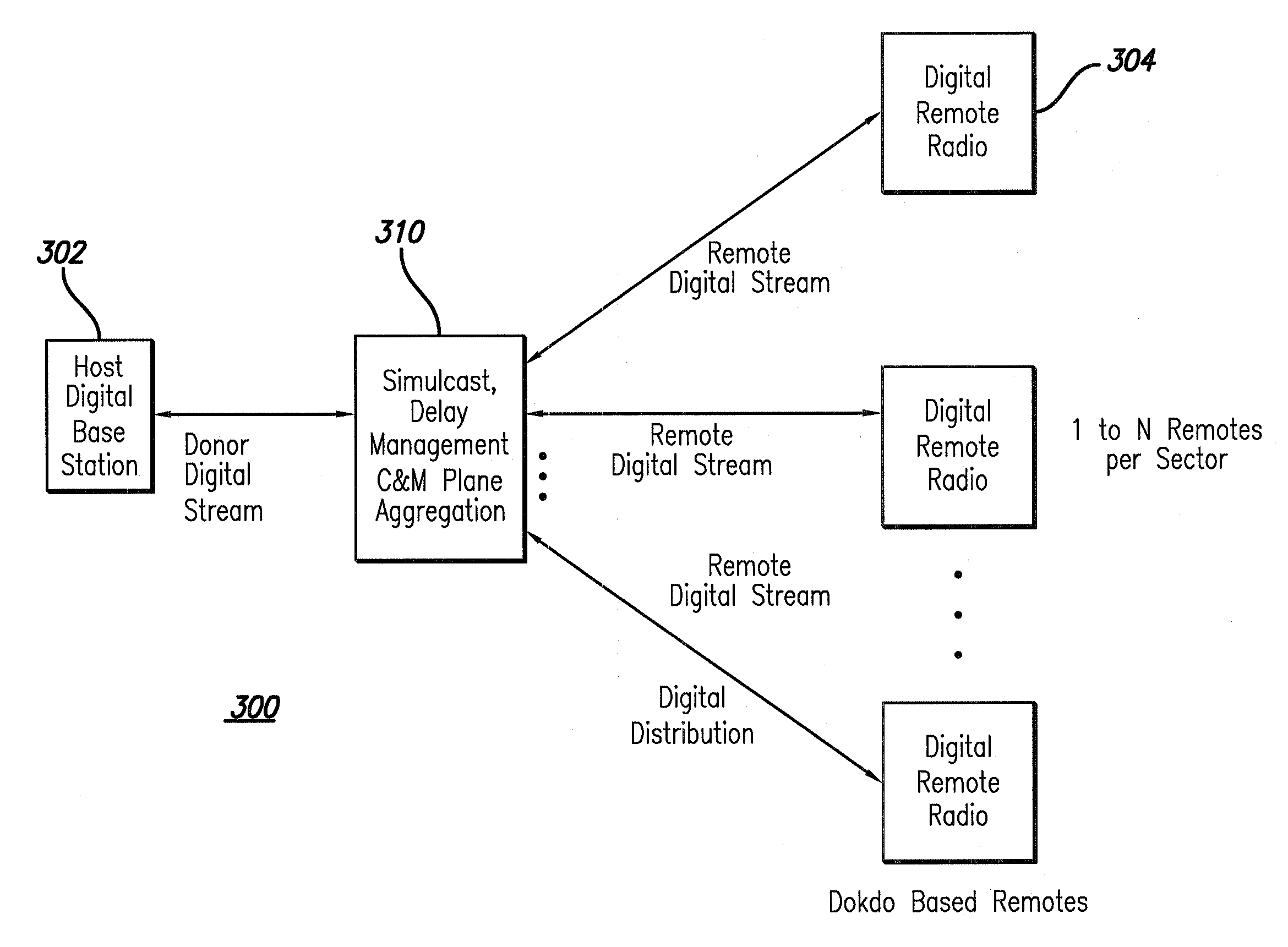
[0030]FIG. 3 is a preferred embodiment of the invention illustrating a simple top level diagram of a digital host base station 102 in conjunction with a Distributed Antenna System (DAS) network 300 with simulcast capability.

[0031]As shown, FIG. 3 is a block schematic drawing of a host digital base station and Digital Distributed Radio with direct digital connection to and from the donor base station with digital distribution to the Digital Remote Radios. This has a digital multiplexed communication signal with a timing requirement incompatible with conventional simulcast techniques, as discussed above. For this and subsequent diagrams, a specific digital base station interface (CPRI) will be used as an example for labeling and description...


PUM


Abstract

A digital distributed antenna system (DDAS) that regains the capability to perform simulcast to multiple simulcast groups while using a base station's direct digital output is provided. The User Plane data is adapted for simulcast and also for eliminating time delay ambiguities across multiple simulcast digital radios. In addition, the Control and Management Plane is aggregated across multiple remote units to allow a non-modified donor digital base station to control simulcast groups. The result is a low cost digital DAS that can efficiently distribute the capacity of a digital base station to solve coverage and capacity requirements in a manner similar to that now accomplished using a traditional base station with RF in/out.

Description

RELATED APPLICATION INFORMATION[0001]The present application claims the benefit under 35 USC 119(e) of U.S. provisional patent application Ser. No. 61 / 008,763 filed Dec. 21, 2007, the disclosure of which is incorporated herein by reference in its entirety.FIELD OF INVENTION[0002]The present invention relates to wireless communications systems and methods. More specifically, the present invention relates to distributed antenna systems (DAS).BACKGROUND OF THE INVENTION[0003]Current wireless communications systems are directed to providing RF coverage and / or call capacity so that users may connect to the wireless infrastructure. All solutions rely on some means of distributing RF energy ranging from high power, large coverage area towers to low power in-building pico-cells.[0004]There also exists a class of RF enhancement technologies known as RF repeaters. Some are bidirectional RF amplifiers that retransmit the signals received over the air from a host base station. Others are direct...

Claims


Application Information

Patent Timeline
IPC IPC(8): H04W4/00H04B10/00
CPCH04W88/085
Inventor SABAT, JOHNPORTE, DAVID
Owner INTEL CORP
Why Eureka
Try Eureka