
System and method for accurate lift-detection of an input device

a technology of input device and lift detection, which is applied in the direction of cathode-ray tube indicators, instruments, electric digital data processing, etc., can solve the problems of changing the distance between the capacitor electrodes, and achieve the effect of accurate detection of lift on any surface, improved tracking, and tunable lift detection

Inactive Publication Date: 2009-05-28
LOGITECH EURO SA
View PDF65 Cites 55 Cited by
  • Summary
  • Abstract
  • Description
  • Claims
  • Application Information

AI Technical Summary

Benefits of technology

[0016]Embodiments of the present invention include a system and method that enables an optical device to accurately detect lift on any surface, even with improved tracking. Embodiments of the present invention to continuously and / or directly determine height of the lift from the surface, and allow the lift-detection to be tunable. Embodiments of the present invention allow for optimization of the lift-detection module in an input device.
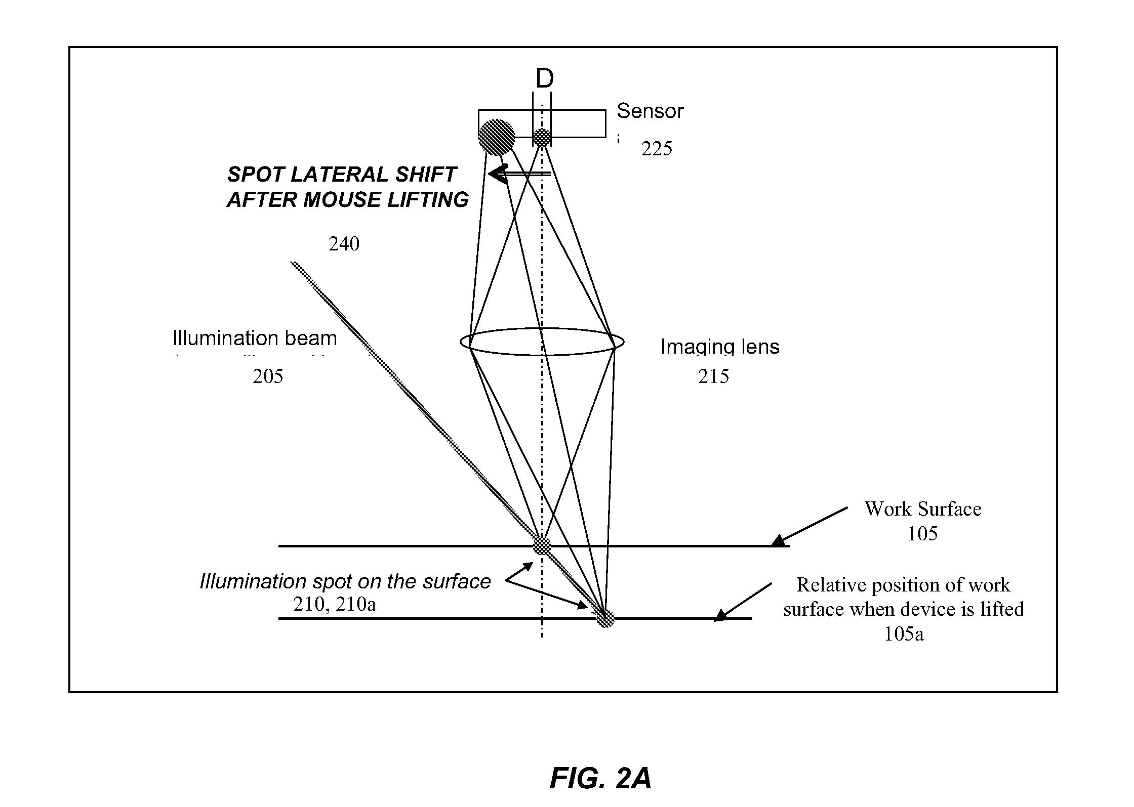
[0017]Various methods are employed for lift-detection in accordance with embodiments of the present invention. Beam triangulation is one way in which lift of an input device can be detected. In one embodiment, confocal geometry with extended depth of focus is used. In accordance with one embodiment, a single light source is used. In accordance with one embodiment, multiple light sources are used. Thus the triangulation computations can be based on the movement of more than one spot (each spot corresponding to a light source), and thus more accurate lift detection is possible. In accordance with an embodiment of the present invention, an optically based lift detection module is separate from the optical tracking module. For instance, the light source and / or the sensor used for the lift-detection module are different from the light source and / or sensor used for the optical tracking engine. This facilitates independent optimization of components for purposes of lift detection and for purposes of tracking.
[0020]In accordance with an embodiment of the present invention, a mechanical plunger with an elastic membrane is used for lift detection. The mechanical plunger remains inside the mouse when the mouse is resting on the table, but protrudes from the mouse (due to gravity, a spring or other elastic material, etc.) when the mouse is lifted. An elastic membrane covering the plunger prevents dirt particles from contaminating the device, and can also be helpful in dealing with electro-static discharge (ESD). In one embodiment, an obturator activates / de-activates a switch used for lift-detection. In one embodiment, such an optical barrier can be obliquely placed between a source and a detector, thus allowing for progressive detection of lift.

Problems solved by technology

Further, the distance between the capacitor electrodes changes, due to the change in compression of the inserted material.

Method used


Image

  • System and method for accurate lift-detection of an input device
  • System and method for accurate lift-detection of an input device
  • System and method for accurate lift-detection of an input device

Examples


Embodiment Construction

[0038]The figures (or drawings) depict a preferred embodiment of the present invention for purposes of illustration only. It is noted that similar or like reference numbers in the figures may indicate similar or like functionality. One of skill in the art will readily recognize from the following discussion that alternative embodiments of the structures and methods disclosed herein may be employed without departing from the principles of the invention(s) herein. It is to be noted that although the following description of the preferred embodiments of the present invention is presented in the context of an optical mouse, there are other devices that can use the present invention such as, for example, an optical scanner, an optical digital writing system (e.g., Logitech IO pen by Logitech, Inc. of Fremont, Calif.), and in some cases, even a conventional opto-mechanical input device.

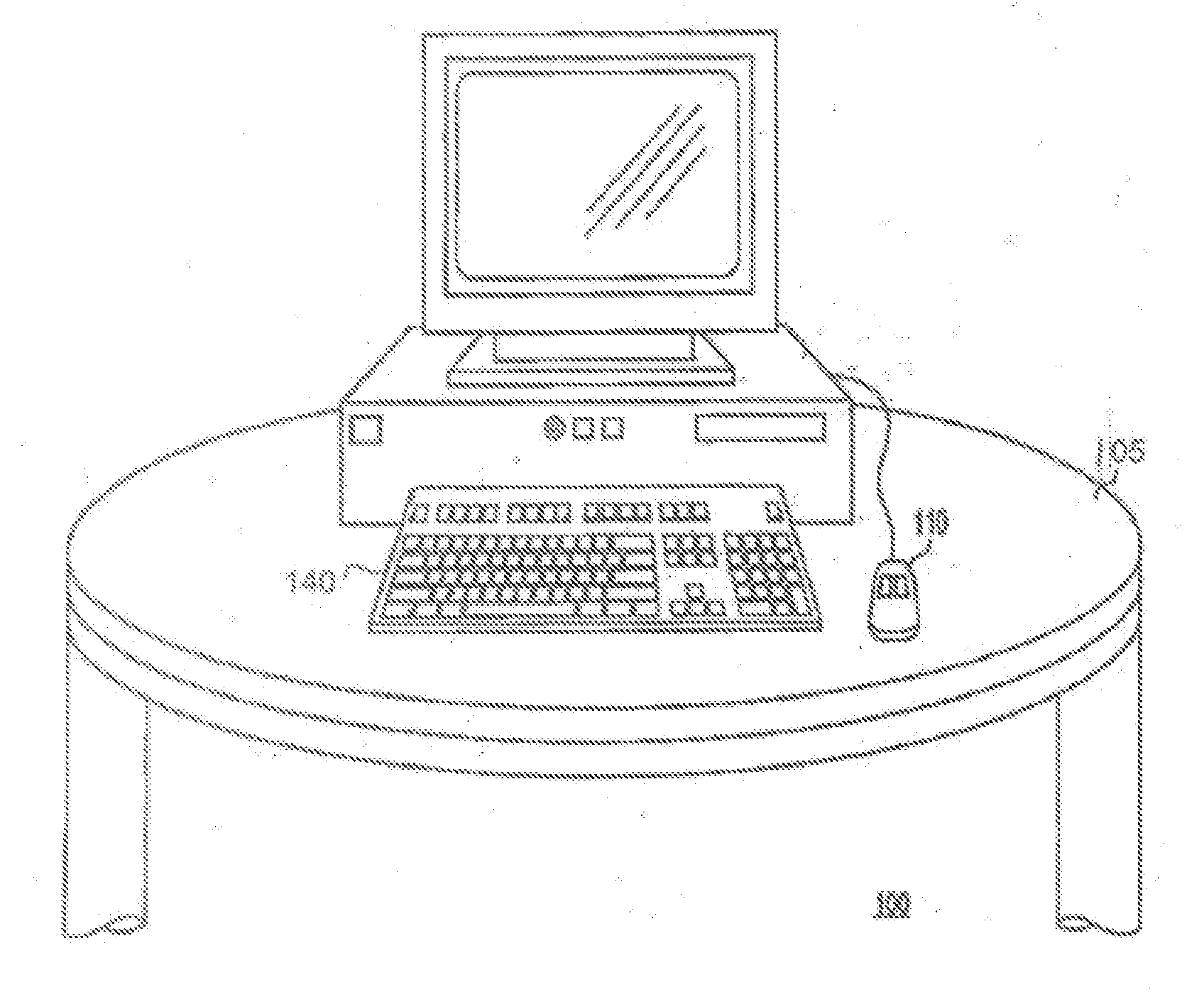
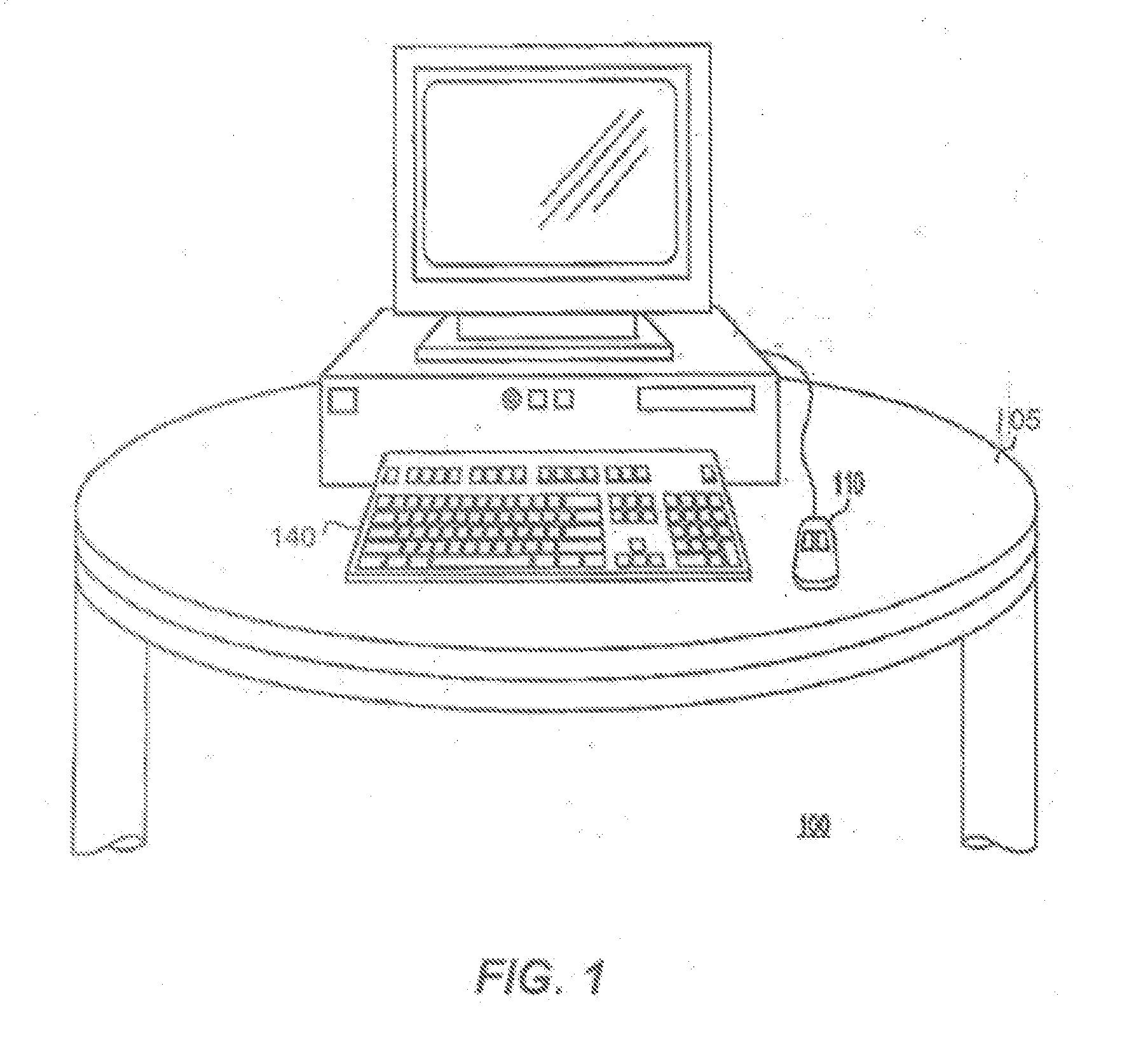
[0039]FIG. 1 shows a sample diagram of a conventional computer system 100 including two input devices, a...


PUM


Abstract

Various systems and methods are employed for lift-detection. Beam triangulation can be used, and in one embodiment, an optical lift detection module is separate from the optical tracking module. In one embodiment, a capacitive lift detection technique is used. A capacitor is built into the bottom case of the mouse. When the mouse is resting on a surface, the surface material serves as a dielectric for the capacitor, while air serves as the dielectric when the mouse is lifted. This dielectric change leads to a change in the capacitance value, leading to detection of lift. In one embodiment, a capacitor with an easily compressable material inserted between the two electrodes is used. In another embodiment, a mechanical plunger with an elastic membrane is used for lift detection. Lift detection can be tunable and / or customizable. The actual height of the life can be detected, rather than simple on-off notifications.

Description

CROSS-REFERENCES TO RELATED APPLICATIONS[0001]This application claims the benefit of, and priority to, U.S. Provisional Application No. 60 / 990,493, entitled “System and Method for Accurate Lift-Detection of an Input Device”, filed on Nov. 27, 2007, which is hereby incorporated by reference herein in its entirety.BACKGROUND OF THE INVENTION[0002]1. Field of the Invention[0003]The present invention relates generally to input devices, and more particularly, to lift detection in input devices.[0004]2. Description of the Related Arts[0005]Input devices, such as a mouse or a trackball, are well known peripheral devices in data processing environments. Input devices allow for cursor manipulation on a visual display screen of a personal computer or workstation, for example. Cursor manipulation includes actions such as rapid relocation of a cursor from one area of the display screen to another area or selecting an object on a display screen. Over years, input devices have evolved to include ...

Claims


Application Information

Patent Timeline
IPC IPC(8): G06F3/02
CPCG06F3/0317G06F3/03545G06F3/03543
Inventor CONSTANTIN, CHRISTOPHEBIDIVILLE, MARCTHEYTAZ, OLIVIERMATHIS, OLIVIERKARAMATA, BORISCHAUVIN, NICOLASROBERT, JACQUES
Owner LOGITECH EURO SA
Learn More