Twin-wire press

Inactive Publication Date: 2010-03-23
VALMET TECHNOLOGIES INC
View PDF9 Cites 0 Cited by
  • Summary
  • Abstract
  • Description
  • Claims
  • Application Information

AI Technical Summary

Benefits of technology

[0011]These objects are thus achieved with a frame for a twin-wire press according to the present invention. The frame comprises a first and a second pair of longitudinal side members. The respective pairs of side members comprises an upper side member and a lower side member and are arranged along each opposite longitudinal long side of the twin-wire press, between which first and second pair of side members rolls are arranged to be attached in the twin-wire press. Furthermore, the frame comprises several transverse beams arranged between the first and the second pair of opposite side members. The frame includes respective side members that at least partially comprise sections of flat sheet metal elements. Upper and lower side members of the respective pairs of side members are mutually releasably connected by distance elements. The sheet metal element is formed such that it permits a certain extent of curving in a vertical plane, transverse to the horizontal plane, which facilitate accessibility to the space between the upper and lower rolls for performing work with maintenance, exchange of wire and cleaning.
[0012]In view of the fact that the longitudinal side members of the frame partially comprise flat sheet metal elements, the requirement of a hinge structure that is necessary in conventional twin-wire presses can be completely eliminated. In order to reach the space between upper and lower rolls along a long side of the press, the s

Problems solved by technology

However, this known structure with a hinge joint

Method used


Image

  • Twin-wire press
  • Twin-wire press
  • Twin-wire press

Examples


Example

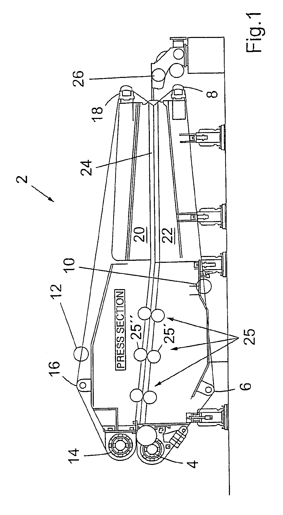
[0018]FIG. 1 shows a twin-wire press 2 according to the present invention. The twin-wire press 2 comprises three lower rolls, namely, a drive roll 4, a control roll 6 and a tensioning roll 8. An endless lower wire 10 runs in a path around the lower rolls, 4, 6 and 8. In a corresponding manner an upper endless wire 12 runs in a path around three upper rolls, namely, a drive roll 14, a control roll 16 and a tensioning roll 18. An upper dewatering table 20, that supports the upper wire 12, and a lower dewatering table 22, that supports the lower wire 10, forms the dewatering space 24 between the wires, 10 and 12, in which the fiber suspension / web M is dewatered. “Press section” refers to an ordinary roll arrangement according to the state of the art that can involve a plurality of roll pairs 25, such as schematically shown in FIG. 1. An inlet box 26 is arranged at one end of the press.

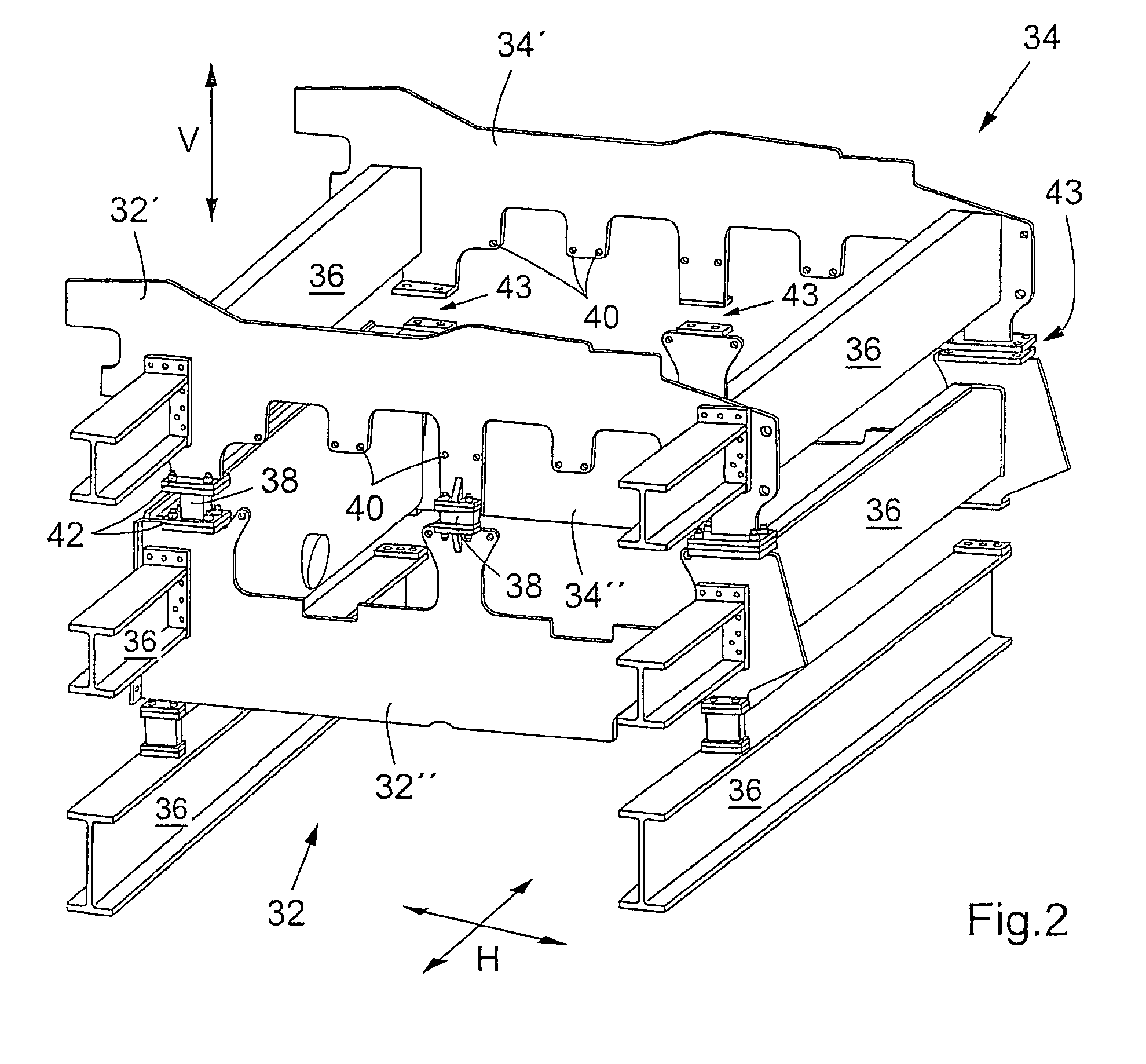
[0019]FIG. 2 shows a frame for a twin-wire press described with reference to FIG. 1, mainly intended a...


PUM


Abstract

A frame for a twin-wire press is disclosed including pairs of side members including upper and lower side members arranged on opposite sides of the press, between which upper and lower rolls are attached, a plurality of transverse beams arranged between the pairs of side members which themselves are sections of flat sheet metal and spacers for mutually releasably connecting the side members with the sheet metal being formed so that it permits a degree of curing in the vertical plane to facilitate access to the space between the upper and lower rolls. A method for exchanging wire in a twin-wire press of this type is also disclosed.

Description

[0001]This application is a 371 of PCT / SE05 / 00850 filed on 3 Jun. 2005.FIELD OF THE INVENTION[0002]The present invention relates to a frame for a twin-wire press and a method for exchange of wire in twin-wire press comprising said frame.BACKGROUND OF THE INVENTION[0003]Twin-wire presses for dewatering of a fiber suspension and forming of a continuous web thereof are previously known. Dewatering of the pulp is usually done from an inlet pulp concentration of 3 to 8 percent by weight to an outlet pulp concentration of 30 to 50 percent by weight. According to the state of the art, such twin-wire presses comprises lower rolls, an endless lower wire running in a path around the lower rolls, upper rolls, and an endless upper wire running in a path around the upper rolls. The two wires co-operate with each other along sections of said paths that run substantially in parallel with each other for dewatering of the fiber suspension between the wires during displacement thereof. An inlet box p...

Claims


Application Information

Patent Timeline
IPC IPC(8): D21H11/00D21H27/00D21FD21F1/00D21F1/80D21F7/00D21F9/00
CPCD21F1/80D21F9/003D21F7/001
Inventor ODMARK, LEIFSVEDBERG, PETERLOFSTRAND, ANDERSLOVGREN, HANS
Owner VALMET TECHNOLOGIES INC
Why Eureka
Try Eureka