Method for manufacturing a weighted base

a manufacturing method and weighted technology, applied in the field of mounting platforms, can solve the problems of curving, lack of portability, and non-planar nature of these and other surfaces, and achieve the effect of convenient breakag

Inactive Publication Date: 2010-03-23
CARNEVALI JEFFREY D
View PDF24 Cites 55 Cited by
  • Summary
  • Abstract
  • Description
  • Claims
  • Application Information

AI Technical Summary

Benefits of technology

[0009]The radially projected spider legs are only intended to space each of the enlarged monolithic masses away from the central hub, and to function as in-gates in the mold for transferring injection molding material from the central hub to the enlarged end masses during the injection molding process when the injection molding material is introduced through a sprue into the central hub. Therefore, the spiders legs are severely necked-down before expanding into the substantially widened and thickened monolithic end masses at their outer ends distal from the central hub so as to be easily breakable at a later processing stage. The enlarged monolithic end masses are both significantly thicker and significantly wider than the breakable in-gate spider legs. In particular, the necked-down spider legs are intended to be broken, either in a later stage of production, or by the end user before use. Only when the spider legs are broken can the novel weighted mounting platform be used as intended for conforming to a non-planar surface because, until such time as the spider legs are broken, the weighted end masses at their outer ends are substantially rigidly connected in a substantially coplanar relationship with the central hub so as to be constrained from conforming to such a non-planar surface.

Problems solved by technology

Unfortunately, the curving, non-planar nature of these and other surfaces is ill suited to the usually regular mounting surface common to most articles and to the stands and holders provided to support the less regular items.
However, the first two lack portability, while the latter will not adhere to rough, cushioned, or fabric surfaces common in many automobiles.
Unfortunately, this bean bag technology generally requires the assembly of many pieces in multiple assembly steps.
However, although less expensive to produce and more effective in operation than bean bag-type bases, even the monolithic weighted base is limited in its ability to provide the above function in an economically efficient manner.

Method used


Image

  • Method for manufacturing a weighted base
  • Method for manufacturing a weighted base
  • Method for manufacturing a weighted base

Examples


Embodiment Construction

[0026]In the Figures, like numerals indicate like elements.

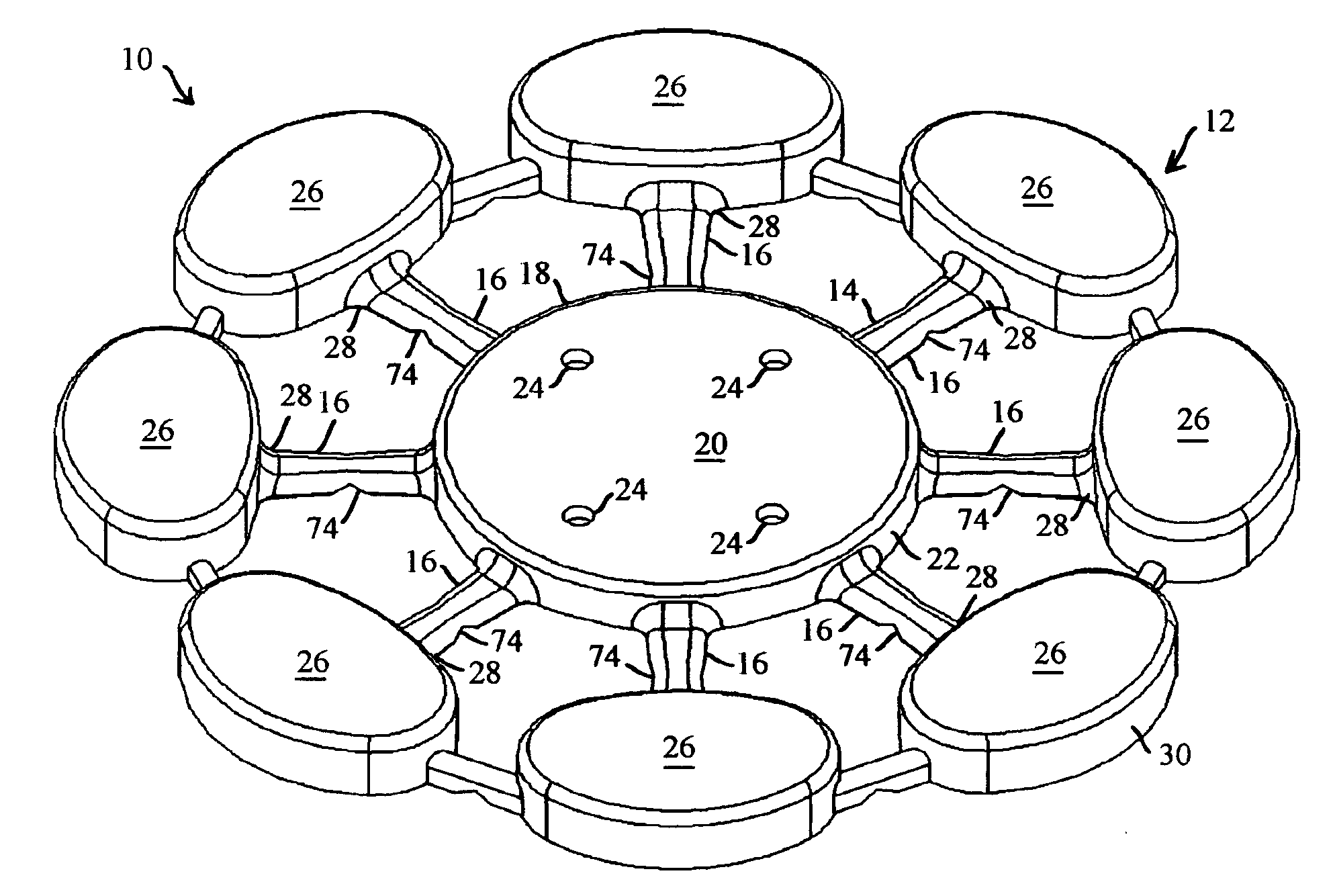
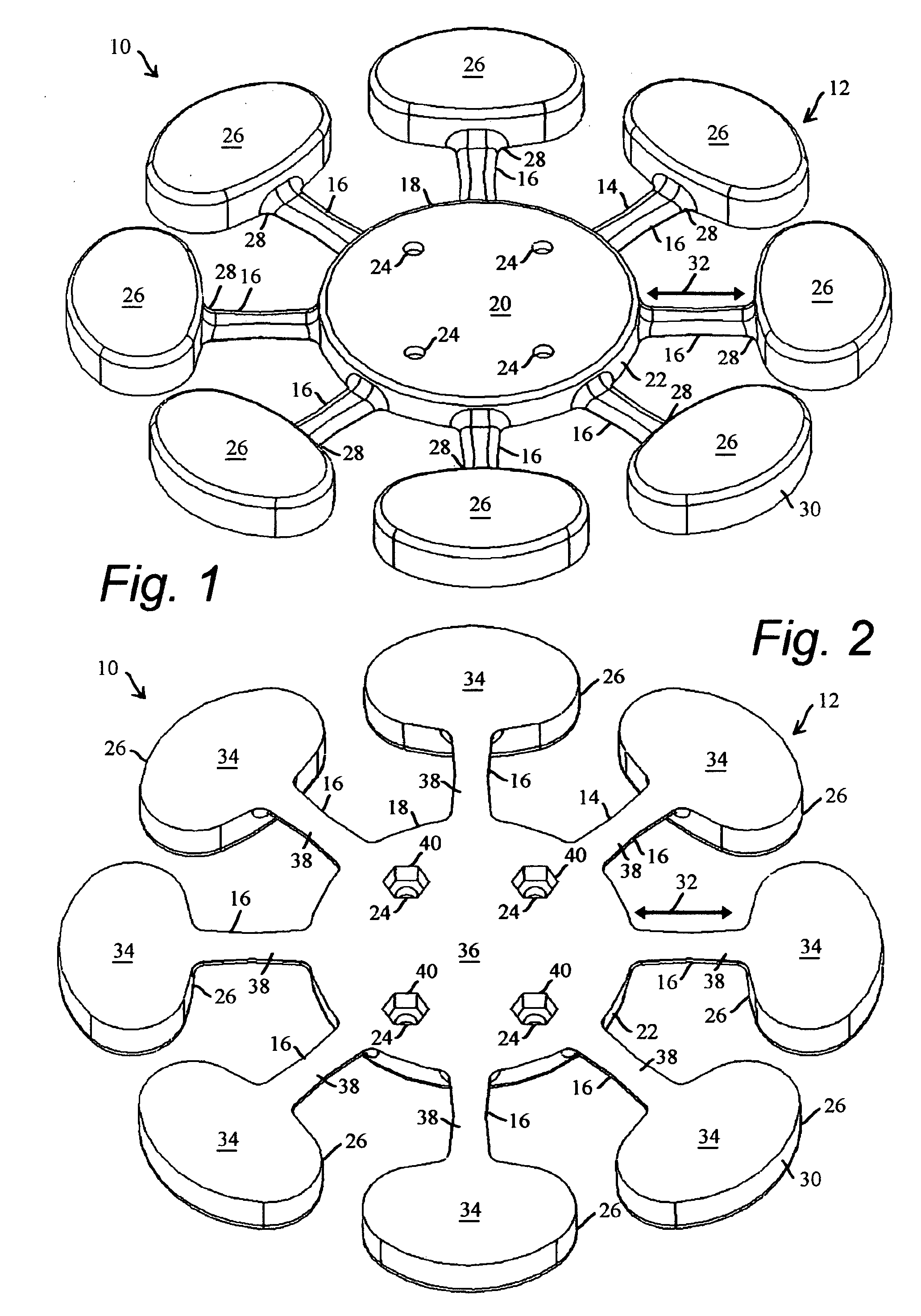
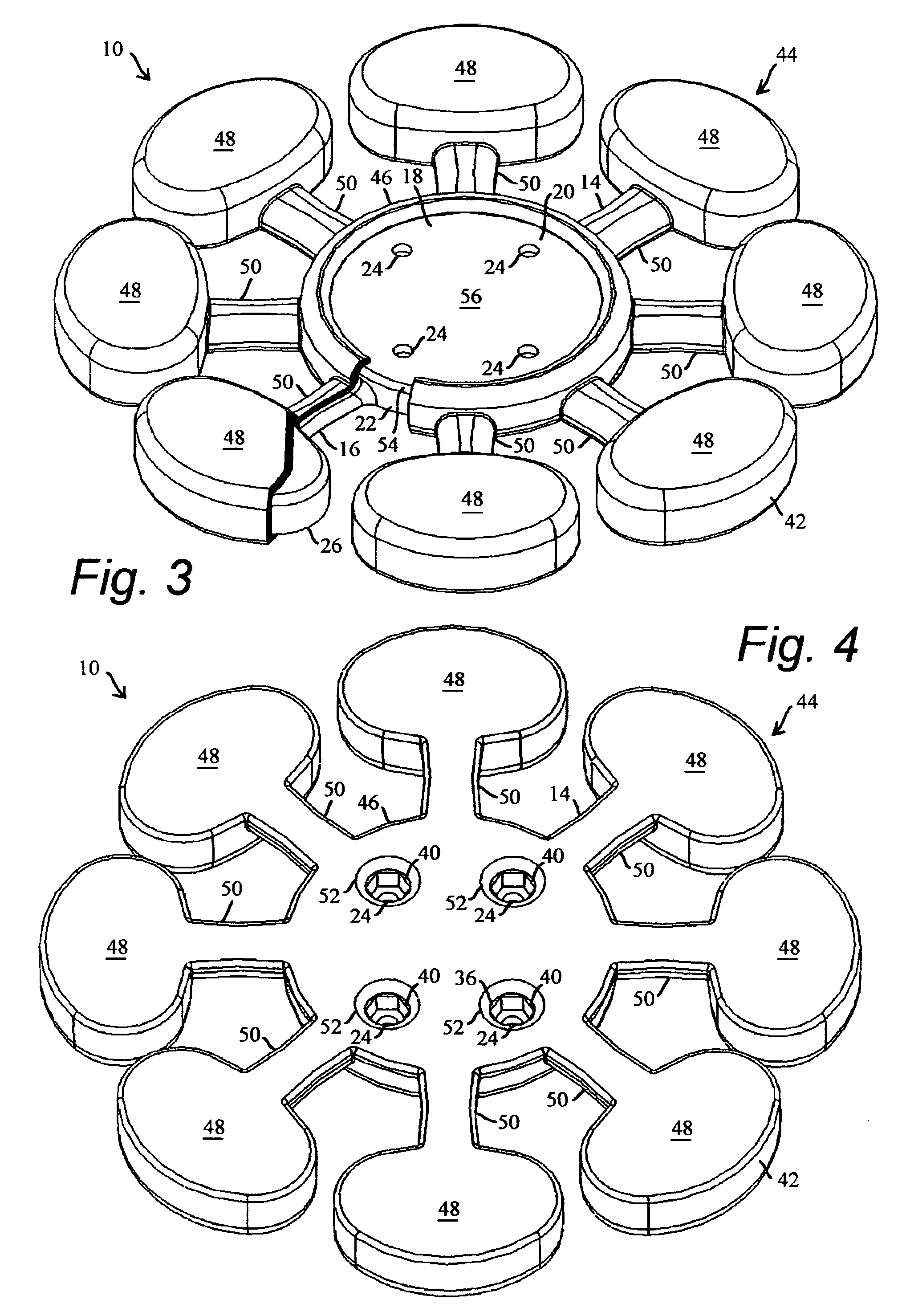
[0027]FIG. 1 is a top perspective view of the present invention illustrated by example and without limitation as a weighted mounting platform 10 conformable to a non-planar surface. The weighted mounting platform 10 includes weighted body structure 12 formed of a web 14 of easily breakable spider legs 16 projected in a substantially radial web from a common large thick monolithic central hub 18 having a substantially planar upper mounting surface20. The weighted mounting platform 10 is illustrated here by example and without limitation as being formed with a plurality of eight of the breakable legs 16 forming the web 14. According to one embodiment, the monolithic central hub 18 is substantially round with the web 14 of breakable legs 16 radiating from sides 22 thereof at regular intervals like spokes of a wheel. Alternatively, the central hub 18 is formed in another shape such as a hexagon or octagon having straight sides w...


PUM

PropertyMeasurementUnit
stress concentrationaaaaaaaaaa
massaaaaaaaaaa

Abstract

A method for manufacturing a weighted mounting platform, the method including: of a first injection moldable material, injection molding a substantially rigid body structure further comprising a substantially central hub with a plurality of legs projecting therefrom and an enlarged mass positioned adjacent to an end portion of at least two or more of the plurality of legs distal from the hub; of a second injection moldable material, injection molding a flexible skin covering at least a portion of the body structure between each enlarged mass and the central hub; and subsequent to the injection molding a flexible skin, freeing the enlarged mass positioned adjacent to an end portion of at least two or more of the plurality of legs for motion relative to the central hub.

Description

FIELD OF THE INVENTION[0001]The present invention relates generally to mounting platforms for supporting articles in an upright orientation relative to a non-planar surface, and in particular to weighted mounting platforms that are conformable to curving and other non-planar surfaces.BACKGROUND OF THE INVENTION[0002]Curving and other non-planar surfaces are common in many vehicles such as automobiles, boats, and airplanes. One example is the dashboard of an automobile, which typically resembles a series of hills and valleys formed by interconnected gently and steeply curving surfaces. Another example is the usually humped console between the bucket seats of an automobile. Often, the driver and passengers desire to place small articles such as coffee cups, cellular phone stands, and map holders on the vehicle dashboard or console. Unfortunately, the curving, non-planar nature of these and other surfaces is ill suited to the usually regular mounting surface common to most articles and...

Claims


Application Information

Patent Timeline
Patent Type & Authority Patents(United States)
IPC IPC(8): B29C45/14
CPCB29C45/0055B29C45/1676B29C45/0013B29K2705/00Y10S248/91
Inventor CARNEVALI, JEFFREY D.
Owner CARNEVALI JEFFREY D
Why Eureka
Try Eureka