Electrooptical distance measuring device

Active Publication Date: 2010-03-23
LEICA GEOSYSTEMS AG
View PDF10 Cites 8 Cited by
  • Summary
  • Abstract
  • Description
  • Claims
  • Application Information

AI Technical Summary

Benefits of technology

[0006]It is the object of the invention to provide an electrooptical distance measu

Problems solved by technology

By means of this fixing step to be carried out in the device, in which an individual electronic component must be moved, manufacture is made more complicated.
In particular, the photodiode cannot already be mechanically fixed rigidly on the

Method used


Image

  • Electrooptical distance measuring device
  • Electrooptical distance measuring device
  • Electrooptical distance measuring device

Examples


Example

DETAILED DESCRIPTION OF THE DRAWINGS

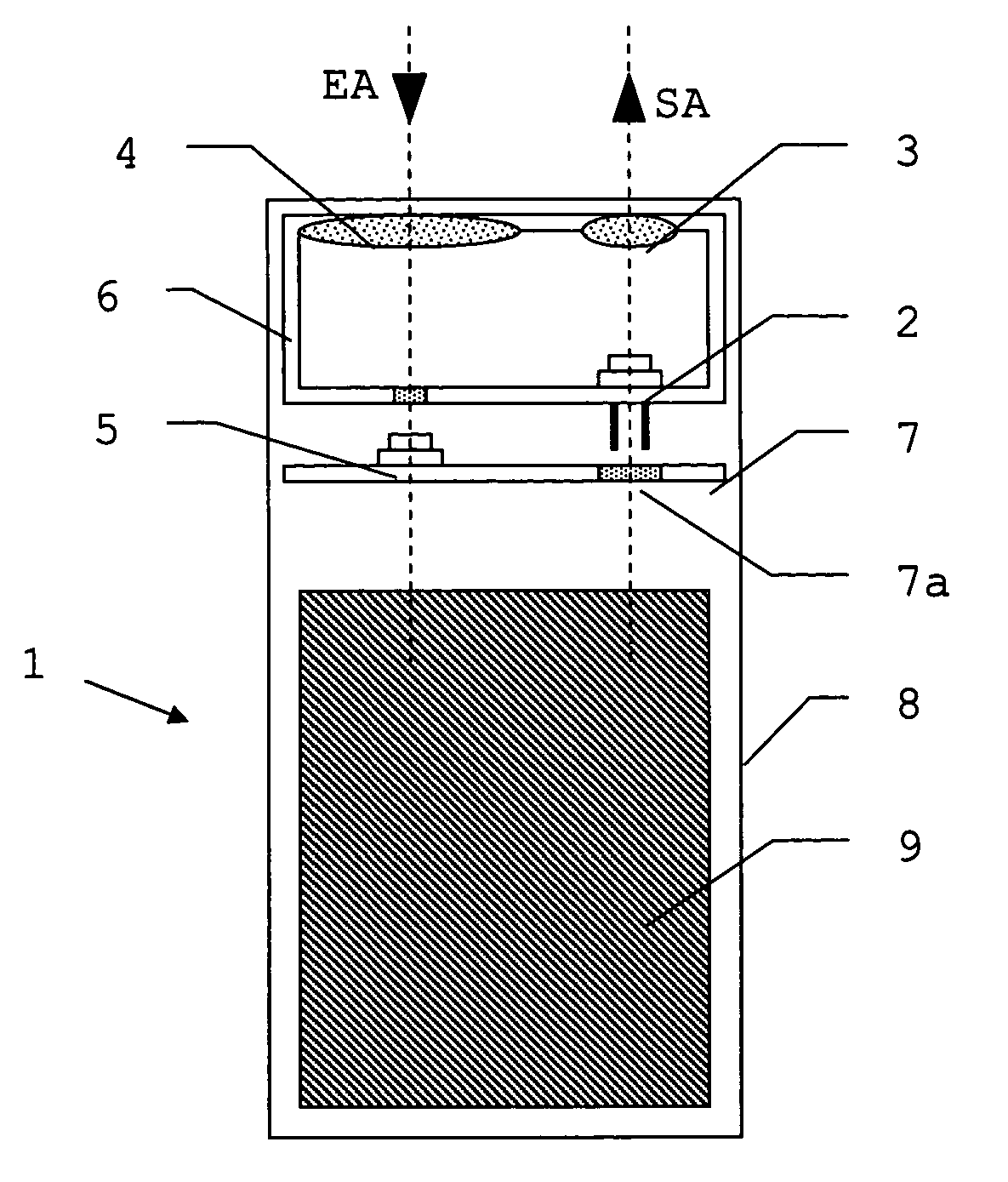
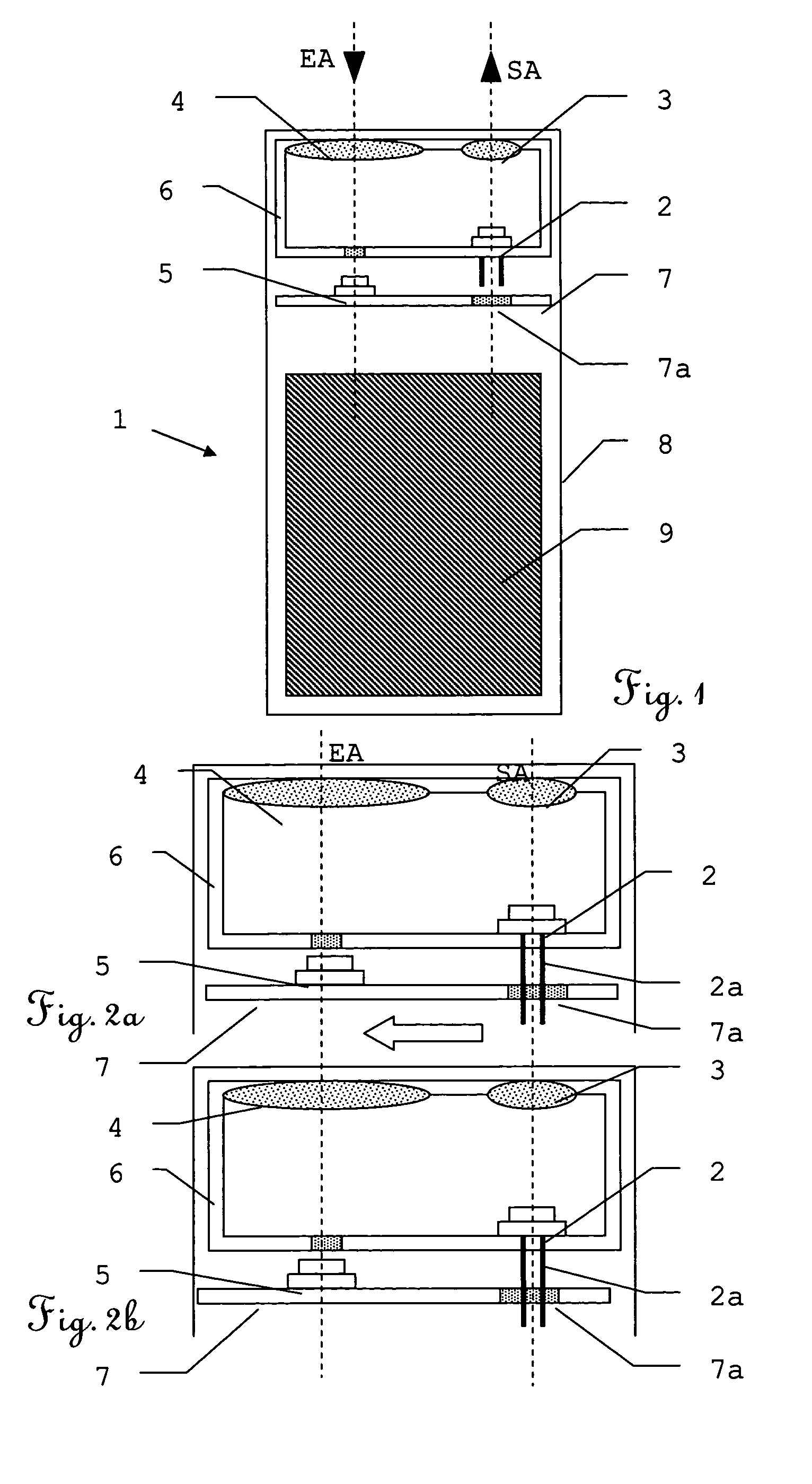
[0031]FIG. 1 shows a first working example of an electrooptical distance measuring device 1 according to the invention, comprising a laser diode 2 as a transmitter, which emits optical radiation or laser light via a transmission optical system 3 having a transmission axis SA for illuminating a measured object. The light reflected by the measured object is received by a receiving optical system 4 having a receiving axis EA and passed to a measuring receiver 5, e.g. an avalanche photodiode. The transmission axis SA and the receiving axis EA are oriented parallel or with only a slight inclination relative to one another, so that the arrangement within the measuring range has a character of beam paths offset parallel relative to one another. The transmission optical system 3 and the receiving optical system 4 can advantageously be arranged on a common optics support 6 which can also hold the laser diode 2 and fix it rigidly relative to the transmissio...


PUM


Abstract

The invention relates to an electrooptical distance measuring device comprising a transmitter that emits optical radiation for lighting an object to be measured, an optical transmitting system which is rigidly mounted in relation to the transmitter and a light collector. A support element is positioned with a measurement receiver and a receiving electronics in relation to the light collector. The support element is rigidly linked with the measurement receiver with regard to at least two directions of movement.

Description

[0001]The invention relates to an electrooptical distance measuring device and a method for adjusting such a distance measuring device.BACKGROUND OF THE INVENTION[0002]Distance measuring devices in the form of hand-held measuring devices or industrial sensors have long been known and are commercially available. Their distance measuring range is up to 200 m and they are used, for example, in construction surveying, for example for the 3-dimensional surveying of rooms. For this purpose, a transmitter emits intensity-modulated radiation, in general wavelengths in the visible range being used, which facilitates the sighting of the measuring points. The radiation is reflected or scattered by the measured object and picked up by the receiver. The distance to the measured object is obtained on the basis of the phase position of the modulated radiation relative to the transmitter.[0003]Such a measuring device is disclosed, for example, in EP 0 701 702. In this device, a semiconductor laser ...

Claims


Application Information

Patent Timeline
IPC IPC(8): G01B11/14
CPCG01S7/481G01S7/4972G01S17/36
Inventor SPRENGER, FRANZ
Owner LEICA GEOSYSTEMS AG
Why Eureka
Try Eureka