Transparent wireless bridge route aggregation

a wireless bridge and route technology, applied in the direction of data switching by path configuration, digital transmission, data switching networks, etc., can solve the problems of multiple wireless bridges, slow wireless bridges, and the stp protocol likely to break the bridging loop, so as to increase the bandwidth and robustness of the wireless path

Active Publication Date: 2010-03-23
CISCO TECH INC
View PDF22 Cites 12 Cited by
  • Summary
  • Abstract
  • Description
  • Claims
  • Application Information

AI Technical Summary

Benefits of technology

[0007]In an example embodiment, there is described herein a “Wireless Route Aggregation Protocol” (WRAP) that is used to aggregate multiple wireless links into a WRAP “route bundle” that functions as a single logical LAN bridge link. WRAP link aggregation can be used for example to increase the bandwidth and robustness of the wireless path between two wired Ethernet LANs.

Problems solved by technology

However, wireless bridges tend to be slower so it is often desirable to employ multiple wireless links between two Ethernet LANs.
However, the deployment of multiple wireless bridges introduces other problems.
However, blocking the Ethernet link between two Ethernet switches can introduce another problem known as “secondary LAN fragmentation”: If the STP root bridge is located in the primary Ethernet LAN and the STP cost of two or more relatively slow wireless links is similar, then the STP protocol will likely break the bridging loop by blocking a high-speed Ethernet link on an Ethernet switch in the secondary Ethernet LAN.
User configurations can be used to resolve the fragmentation problem; however, user configurations in larger more complex networks are not practical.
The user must explicitly configure the aggregation links; therefore the protocols cannot automatically adapt to lost links and new links.
Wireless bridging links are far less stable than wired bridging links.
Therefore, an entire aggregated link is susceptible to the failure of a single device.
If frames from a single Ethernet station are directed over more than one path, then a “path flapping problem” is introduced, where the source-learned path to the station, in a transparent Ethernet LAN, is constantly changing.
However, the path flapping problem cannot be resolved by simply restricting all traffic for a single station to a single aggregation link

Method used


Image

  • Transparent wireless bridge route aggregation
  • Transparent wireless bridge route aggregation
  • Transparent wireless bridge route aggregation

Examples


example embodiments

DESCRIPTION OF EXAMPLE EMBODIMENTS

[0023]This description provides examples not intended to limit the scope of the invention, as claimed. The figures generally indicate the features of the examples, where it is understood and appreciated that like reference numerals are used to refer to like elements.

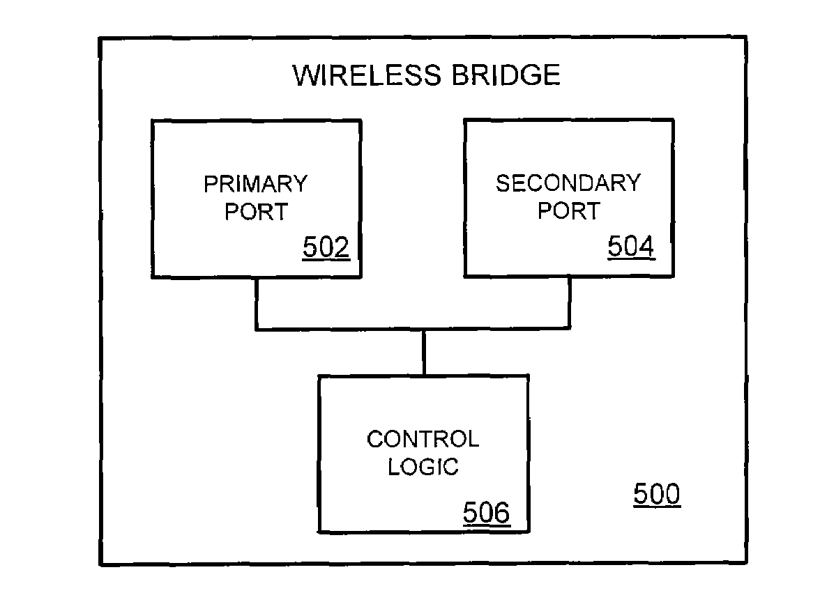
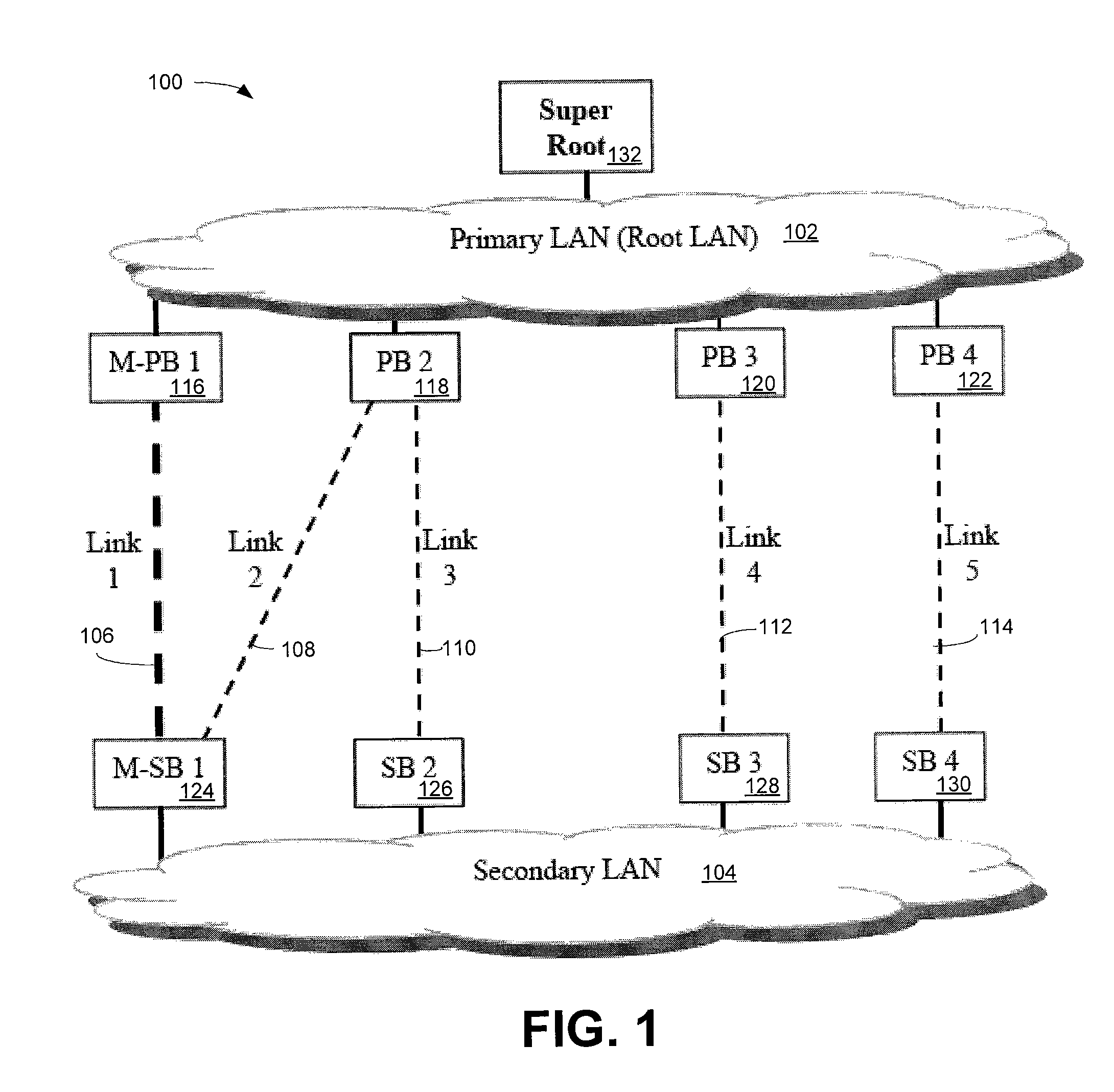
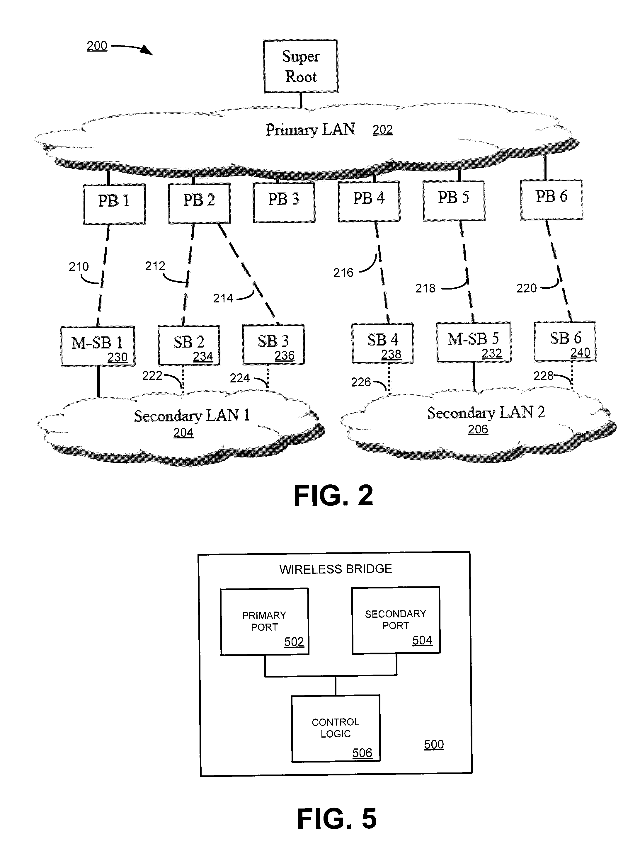
[0024]In an example embodiment, there is described herein a “Wireless Route Aggregation Protocol” (WRAP) that is used to aggregate multiple wireless links into a WRAP “route bundle” that functions as single logical LAN bridge link. WRAP link aggregation can be used, for example, to increase the bandwidth and robustness of the wireless path between two wired Ethernet LANs.

[0025]A “link” is used herein to refer to a wireless link between two radios—one in each of two wireless bridges. A link is terminated by two Link Endpoints—one in each wireless bridge. In an example embodiment, a Link Endpoint is identified by a 48-bit 802 address. A single wireless bridge has 1 or more radios and each ...


PUM


Abstract

In an example embodiment, there is described herein a “Wireless Route Aggregation Protocol” (WRAP) that is used to aggregate multiple wireless links into a WRAP “route bundle” that functions as a single logical LAN bridge link. WRAP link aggregation can be used for example to increase the bandwidth and robustness of the wireless path between two wired Ethernet LANs.

Description

BACKGROUND[0001]Wireless bridges can be employed to bridge two Ethernet Local Area Networks (LANs) over a single radio link, such as an IEEE (Institute of Electrical and Electronics Engineers) 802.11 link. This can obviate the need for wiring and can be useful in situations where wiring is prohibitively expensive. However, wireless bridges tend to be slower so it is often desirable to employ multiple wireless links between two Ethernet LANs.[0002]However, the deployment of multiple wireless bridges introduces other problems. For example, if two (or more) wireless links are coupled to switches to couple a secondary Ethernet LAN to a primary Ethernet LAN, a bridging loop exists unless the spanning tree protocol (STP) used by the switches (e.g. an 802.1D STP) blocks an Ethernet link between the wireless bridges or all but one of the wireless links. However, blocking the Ethernet link between two Ethernet switches can introduce another problem known as “secondary LAN fragmentation”: If ...

Claims


Application Information

Patent Timeline
Patent Type & Authority Patents(United States)
IPC IPC(8): H04L12/46
CPCH04L12/462H04L45/48H04W40/24
Inventor MEIER, ROBERTRAHMAN, SHAHRIAR
Owner CISCO TECH INC
Why Eureka
Try Eureka