Molded wall flashing kick out

a technology of molded wall and kick out, which is applied in the direction of roofs, snow traps, constructions, etc., can solve the problems of reducing the effectiveness of kick out plates, reducing the possibility of kick out plate formation reducing the possibility of kick out plate formation. oversight or incorrect construction, simple design and construction, and the effect of reducing the possibility of kick out plate formation

Inactive Publication Date: 2010-03-30
NELSON ROBERT W
View PDF10 Cites 5 Cited by
  • Summary
  • Abstract
  • Description
  • Claims
  • Application Information

AI Technical Summary

Benefits of technology

[0006]The molded wall flashing kick out of the present invention addresses the aforementioned needs in the art by providing an end cap for use with roof flashing wherein the end cap has a kick out plate for diverting water from the building. The molded wall flashing kick out does not require that a worker form the kick out plate thereby reducing the possibility of kick out plate formation oversight or incorrect construction. The molded wall flashing kick out is usable in a roof deck to side wall transition area and is usable with flashing systems made from a variety of materials. The molded wall flashing kick out, when installed on a building utilizing vinyl siding on the side wall whereat the molded wall flashing kick out is installed has a subsystem that gives the installed vinyl siding a neater overall appearance. The molded wall flashing kick out is of relatively simple design and construction and is easy to use and install.

Problems solved by technology

However, one problem with such flashing installation occurs at the lower terminus of the flashing whereat the roof deck ends.
The problem with this type of kick out plate is that oftentimes workers will completely forget to construct one, leaving the roof vulnerable to water penetration.
Additionally, if the cut or bend is not properly performed by the worker, then the kick out plate may achieve lower effectiveness.
Furthermore, some flashing systems are now being made from plastic material which material is difficult if not impossible to bend inwardly to form the kick out plate.

Method used


Image

  • Molded wall flashing kick out
  • Molded wall flashing kick out
  • Molded wall flashing kick out

Examples


Embodiment Construction

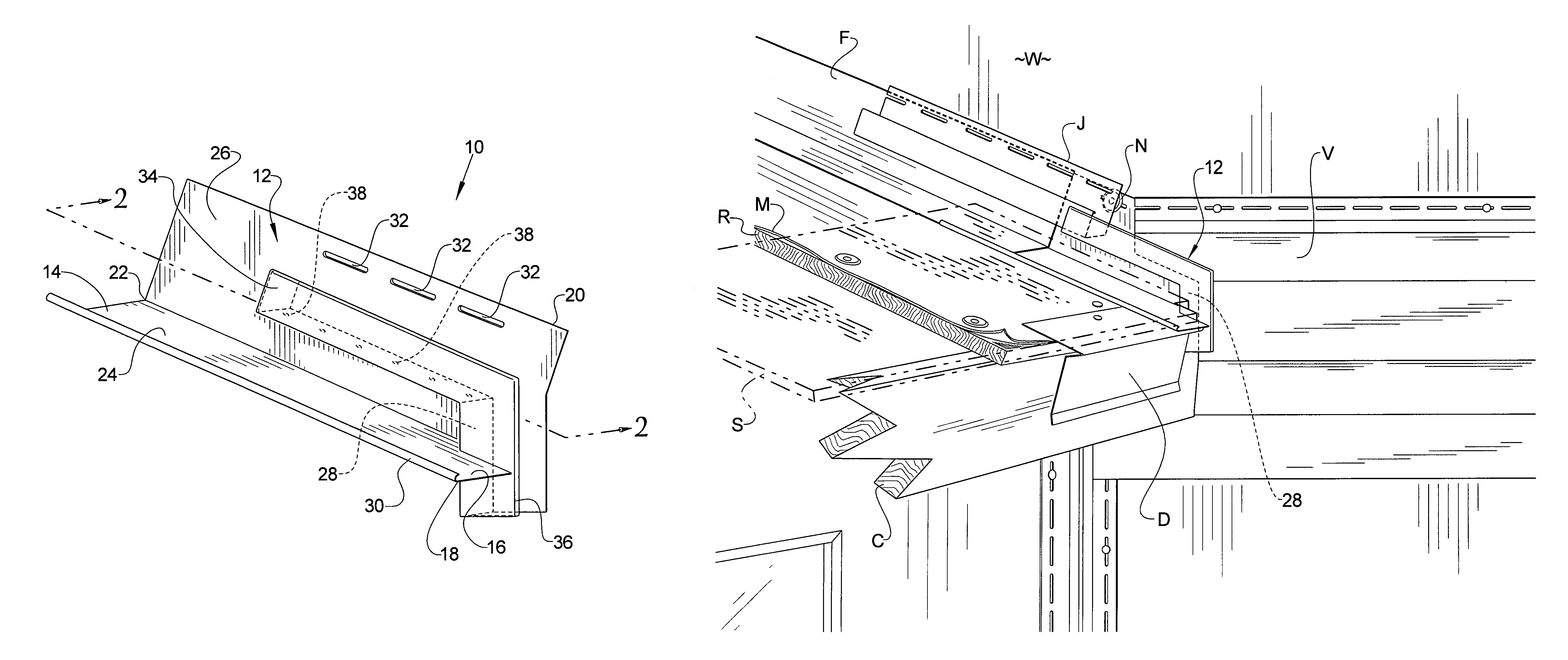
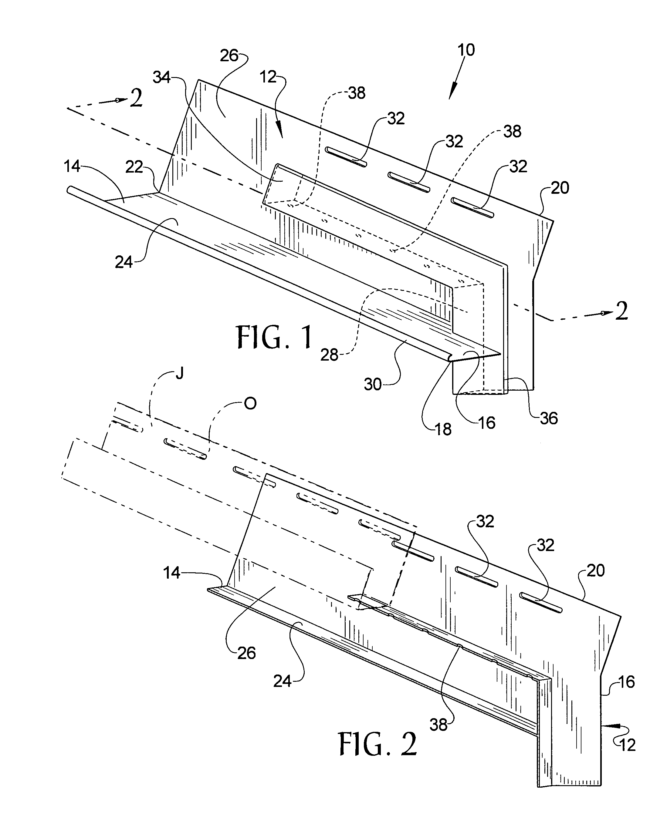
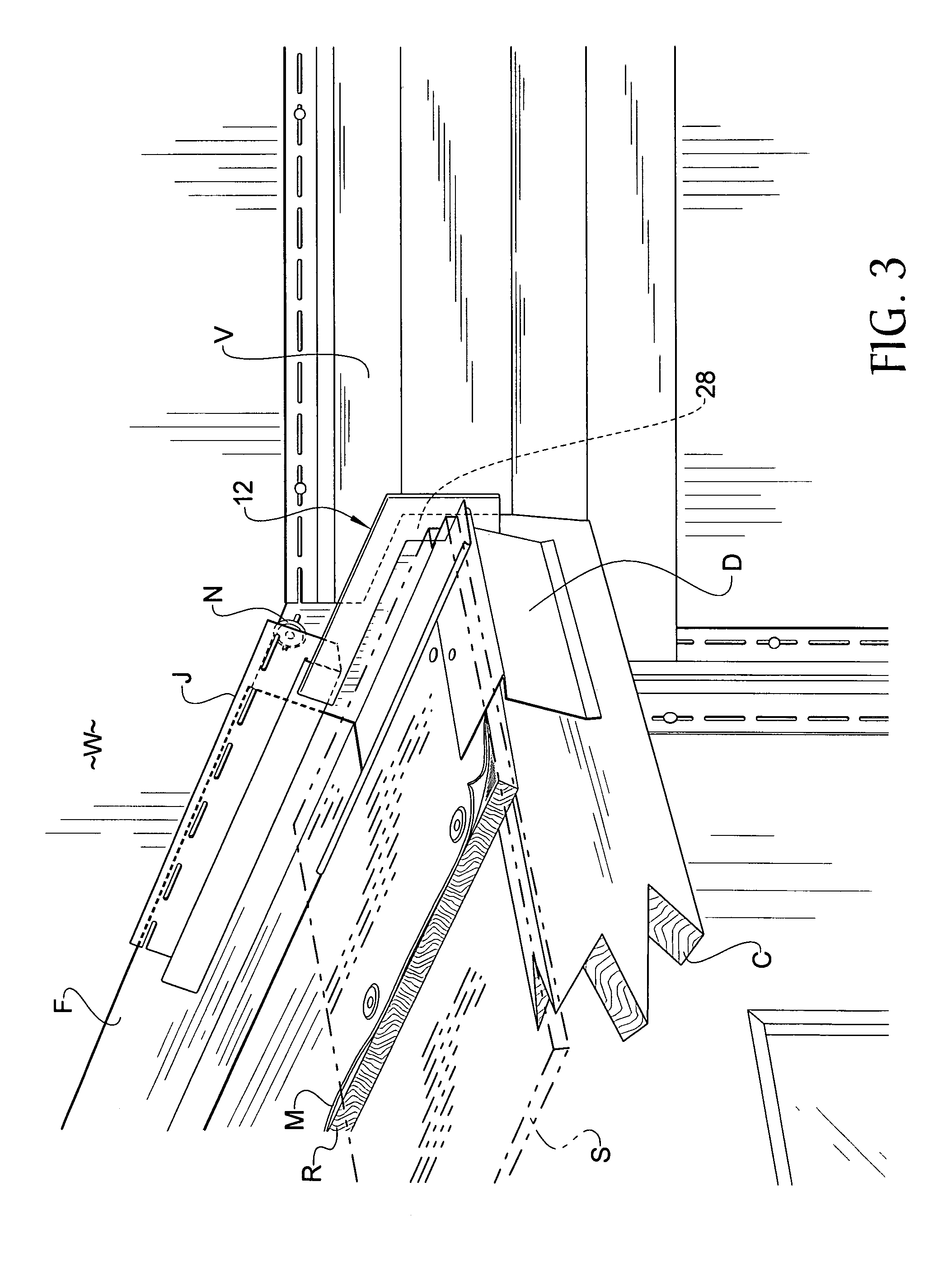
[0012]Referring now to the drawings, it is seen that molded wall flashing kick out of the present invention, generally denoted by reference numeral 10, is comprised of a body member 12 that is a sheet member that has a first end 14, a second end 16, a first side edge 18, and a second side edge 20. A seam 22 extends along the body member 12 between the first end 14 and the second end 16 such that the body member 12 is bent along the seam 22 in order to form a first section 24 having the first side edge 18 and a second section 26 having the second side edge 20. The first section 24 and the second section 26 are angularly offset from one another, the specific angle being the angle between the two sections of a section of flashing F that is used with the flashing end cap 10 of the present invention. A kick out plate 28 extends from the second section 26 of the body member 12 toward the first section 24. The kick out plate 28 is attached to the first section 24. The first side edge 18 of...


PUM


Abstract

A molded wall flashing kick out is designed to be the lower terminus end of a flashing system that is used wherein a roof section terminates against a sidewall of a building. The molded wall flashing kick out has a sheet-like body member that is bent along a longitudinal seam. A kick out plate is integrally formed on the end cap and extends outwardly from a generally vertical section of the body member toward and attaches to a generally horizontal section of the body member. A channel, which may have two sections, is formed on the body member in order to receive a vinyl siding J-channel. The outer edge of the horizontal section of the body member is curled while at least one opening is located on the vertical section of the body member in order to receive a fastener therethrough.

Description

BACKGROUND OF THE INVENTION[0001]1. Field of the Invention[0002]The present invention relates to a molded wall flashing kick out that is installed on a roof side wall interface of a building such that the flashing end cap has an integral kick out plate to divert water away from the building as well as a J-channel receiver for receiving a J-channel used for vinyl siding.[0003]2. Background of the Prior Art[0004]Many buildings have multiple roof levels wherein the end of one of the roof decks terminates and abuts against a side wall of the building. In building the roofing system for such a configuration, a section of flashing is run along the entire length of the roof deck side wall interface. The purpose of the flashing, which is an angled sheet member of monolithic construction, is to help seal the juncture of the roofing deck with that of the side wall in order to prevent water from entering the building at this juncture. Flashing, which is also used in other areas of roof constru...

Claims


Application Information

Patent Timeline
Patent Type & Authority Patents(United States)
IPC IPC(8): E04D1/36
CPCE04D1/36E04D13/0459E04D13/0481E04D2013/0468E04D2013/0486
Inventor NELSON, ROBERT W.
Owner NELSON ROBERT W
Why Eureka
Try Eureka