Construction element and method for manufacturing it

a technology of construction elements and manufacturing methods, applied in the direction of structural elements, containers, building components, etc., can solve the problems of high transportation costs, difficult manipulation of spherical elements, and complex manufacture of spherical elements, and achieve the effect of considerably simplifying the construction of construction elements

Active Publication Date: 2010-03-30
AIRDECK BUILDING CONCEPTS NV
View PDF25 Cites 12 Cited by
  • Summary
  • Abstract
  • Description
  • Claims
  • Application Information

AI Technical Summary

Benefits of technology

[0021]that they are provided with locking parts at the bottom which are designed to be embedded in the concrete layer, thereby either or not catching behind reinforcement elements which are also embedded in this concrete layer, so that a sound interlocking can be realised in the underlying concrete layer, preferably even such that no extra interlocking will have to be further provided on the top side in order to prevent the elements from floating.
[0022]Secondly, the invention also concerns a construction element for forming a reinforced concrete slab, consisting of the combination of at least a hardened concrete layer, at least a number of reinforcement elements and elements extending at least partially from the concrete layer and defining cavities, whereby these elements are designed to be covered with concrete at a later stage, characterised in that the above-mentioned elements are anchored to the construction element, only via a part thereof with which they rest in the concrete layer, being thereby either or not locked to the reinforcement which has been embedded in said concrete layer, by means of an anchoring which is so solid that said elements will at least stay anchored against floating when liquid concrete or cast concrete is poured over them. This offers the advantage that no extra anchoring will have to be further provided on the top side, which makes the construction of the construction element considerably simpler, and which also creates more possibilities to afterwards provide a top reinforcement in the concrete layer as desired.
[0023]Thirdly, the invention also concerns a construction element for forming a reinforced concrete slab, consisting of the combination of at least a hardened concrete layer, at least a number of reinforcement elements and elements extending at least partially from the concrete layer and defining cavities, whereby these elements are designed to be covered with concrete at a later stage, characterised in that the construction element comprises supporting means for a top reinforcement, whereby these supporting means define supporting parts which are situated higher than the top sides of the aforesaid hollow elements. This construction element offers the advantage that, when a top reinforcement is provided on the above-mentioned supporting parts, it is mainly excluded that this top reinforcement rests on the hollow elements, which is advantageous in that, after concrete has been poured over the construction element, the top reinforcement is entirely surrounded by concrete and does not directly make contact with any cavities. At the most will hereby be created a local contact with some of the hollow elements, for example in case the top reinforcement would bend somewhat and would make contact with one of the hollow elements between two supporting parts.
[0024]The invention also concerns a method for manufacturing such a construction element, characterised in that this method at least consists of pouring an amount of concrete in a mould in order to form the above-mentioned concrete layer; in providing the concrete layer with a reinforcement, which is provided in the mould before and / or after the concrete has been poured; in providing hollow elements in the concrete before it has hardened, which are provided with locking parts at their bottom sides, so that they rest in the concrete at least with these locking parts; and in letting the concrete harden, after which the whole is removed from the above-mentioned mould. By fixing the above-mentioned elements defining the cavities directly in the concrete layer by means of locking means, whereby these locking means either exclusively work in conjunction with the concrete or also work in conjunction with a reinforcement provided in the concrete layer, this offers the advantage that no additional steps are required, nor any additional accessories need to be used to provide for a locking from the top.

Problems solved by technology

The hollow spherical elements, which are usually manufactured in another place than the construction elements themselves, result in high transport costs, as they occupy a relatively large volume, although they have a low weight.
Another disadvantage consists in that these spherical elements are difficult to manipulate, especially in an automated process.
Another disadvantage of these known embodiments consists in that their manufacture is rather complex, as the construction element as such already has to be provided with a top reinforcement net, which moreover preferably has to be provided on it in a very precise manner in order to make sure that the spherical elements are locked in the required positions.
Another disadvantage of these known embodiments consists in that the spherical elements rest against the top reinforcement net or can make contact with it as a result of floating, so that, after the liquid concrete has been poured over the construction element, the top reinforcement net cannot be optimally embedded in the concrete.
In practice, this can be remedied by making use of separate locking elements which are connected to the top side of the spherical elements in order to prevent the spherical elements from floating, but this is disadvantageous in that the construction as a whole becomes complex and time-consuming.

Method used


Image

  • Construction element and method for manufacturing it
  • Construction element and method for manufacturing it
  • Construction element and method for manufacturing it

Examples


Embodiment Construction

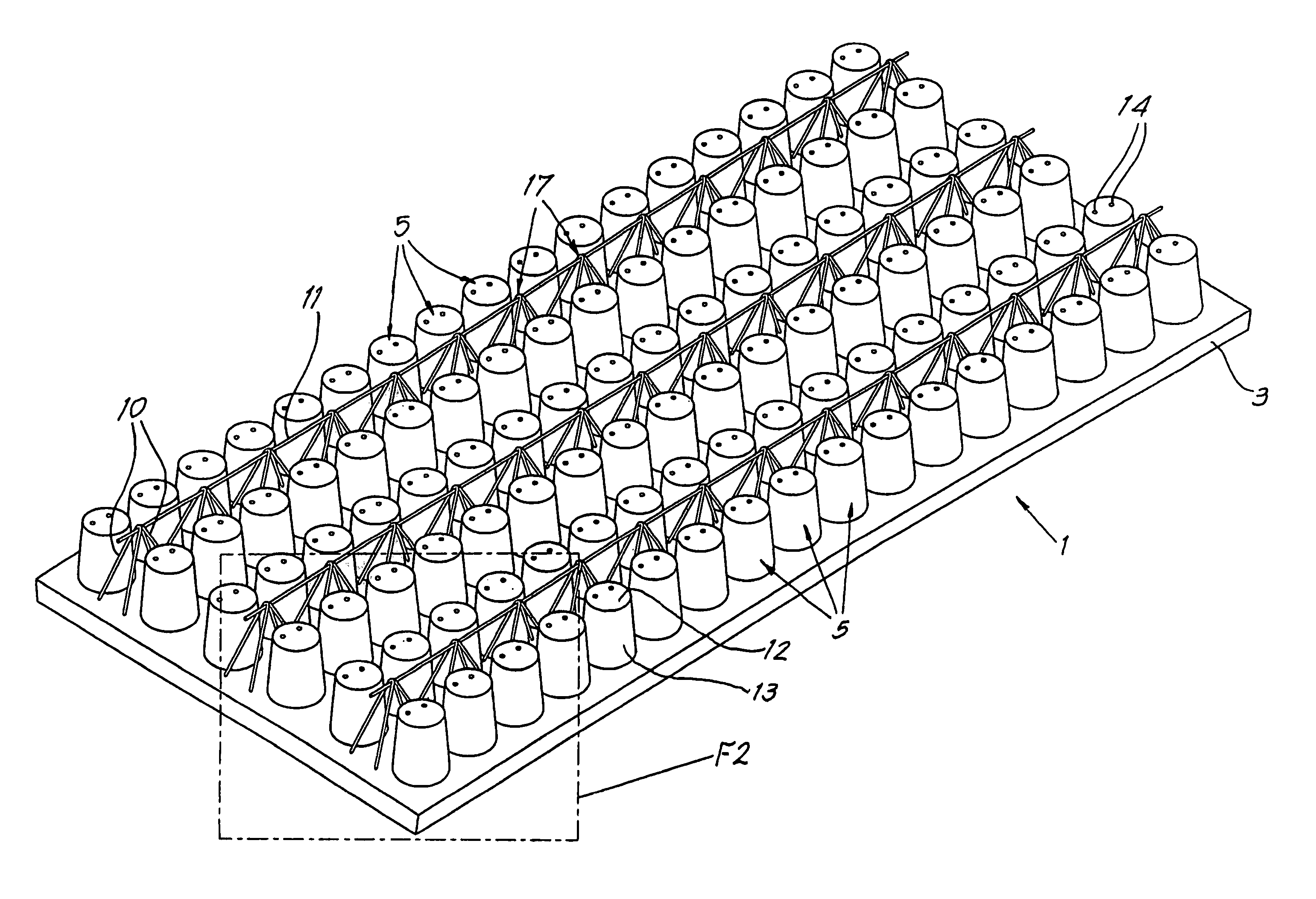
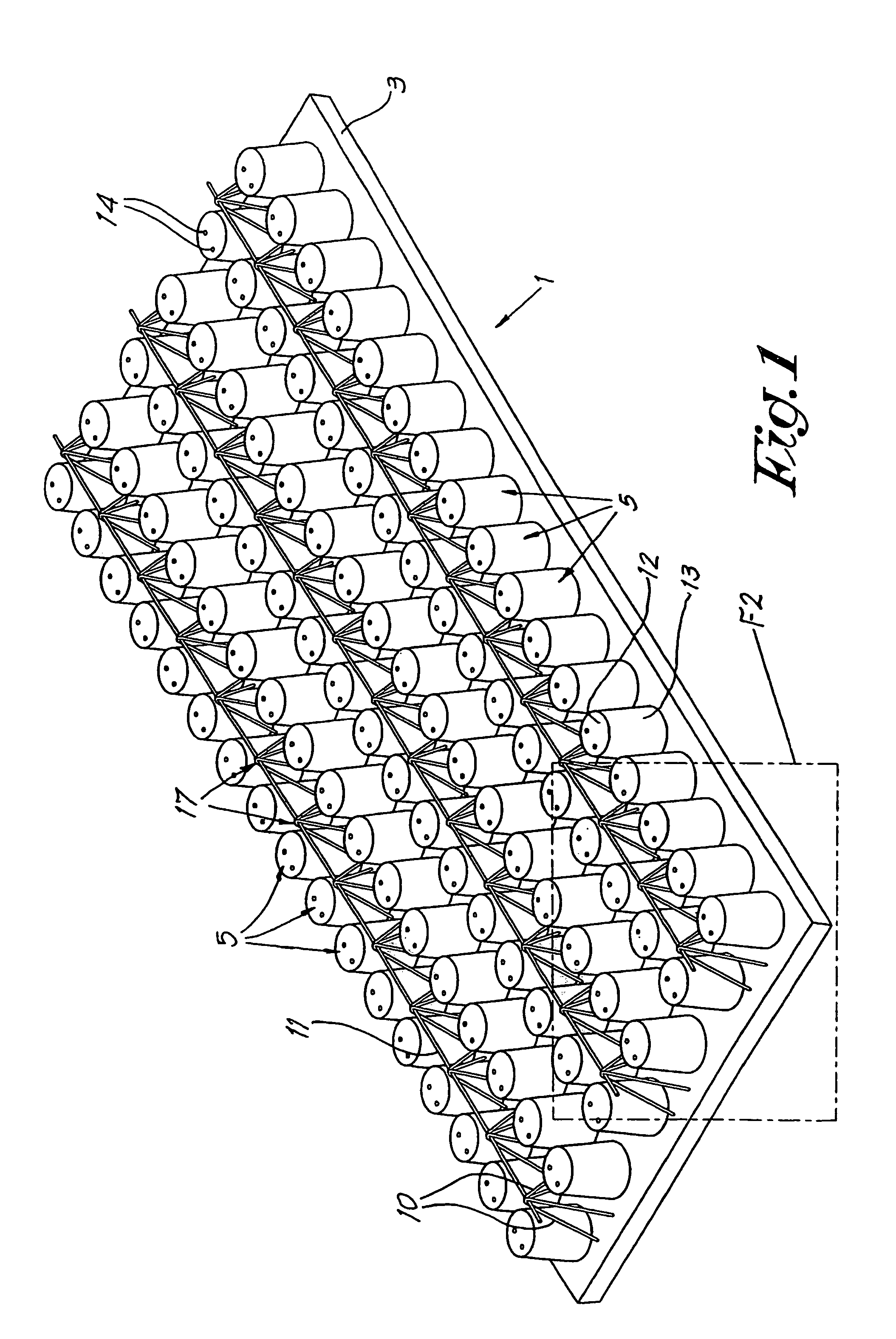
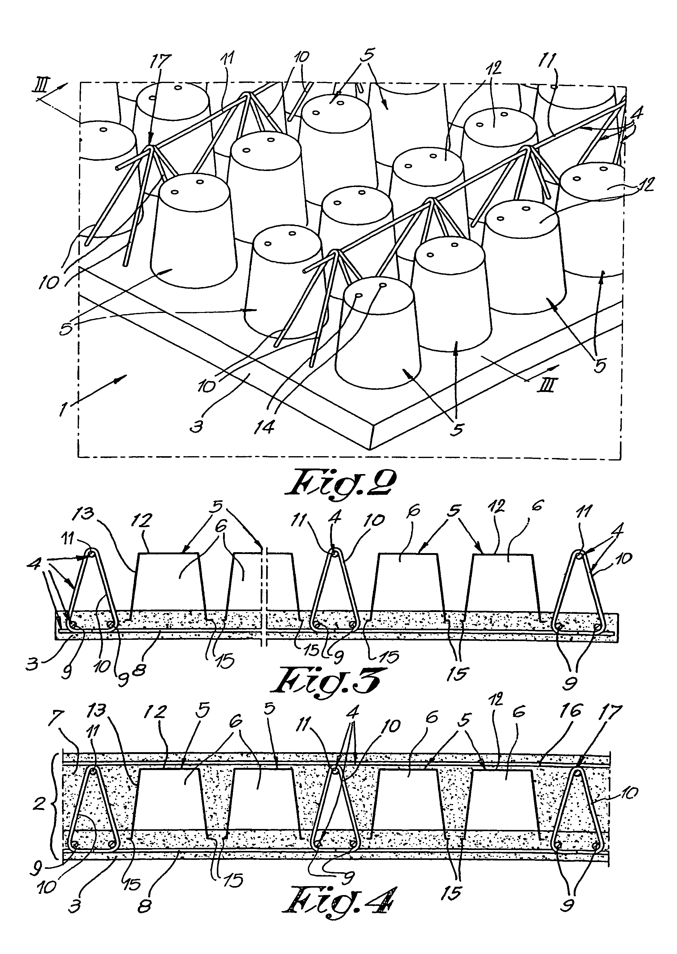
[0033]As represented in FIGS. 1 to 3, the invention concerns a construction element 1 with which can be made a self-supporting reinforced concrete slab 2, as represented in FIG. 4.

[0034]The construction element 1 mainly consists of the combination of at least a hardened concrete layer 3, at least a number of reinforcement elements 4 and elements 5 extending at least partially from the concrete layer 3 and defining cavities 6, whereby these elements 5 are designed to be covered with concrete 7 at a later stage, as can be seen in FIG. 4.

[0035]In the given example, the reinforcement elements 4 consist of reinforcement rods 8-9 in the concrete layer 3, as well as of reinforcement rods 11 born by supports 10 situated at a height above the concrete layer 3. The reinforcement rods 8-9 may consist of separate rods or they may also be part of a reinforcement net.

[0036]Although in the figures, the supports 10 are made triangular, also other shapes are possible, such as for example a rectangul...


PUM


Abstract

Construction element for forming a reinforced concrete slab (2), consisting of the combination of at least a hardened concrete layer (3), at least a number of reinforcement elements (4) and elements (5) extending at least partially from the concrete layer (3) and defining cavities (6), whereby these elements (5) are designed to be covered with concrete (7) at a later stage characterised in that the above-mentioned elements (5) defining the cavities (6) consist of elements (5) which can be mutually nested as such.

Description

BACKGROUND OF THE INVENTION[0001]A. Field[0002]The present invention concerns a construction element, in particular a construction element for forming a reinforced concrete slab, as well as a method for manufacturing such a construction element.[0003]B. Related Art[0004]In particular, it concerns a construction element of the type which consists of the combination of at least a hardened concrete layer, at least a number of reinforcement elements and elements extending at least partially from the concrete layer and defining cavities, whereby these elements are designed to be covered with concrete in the factory or on the building site at a later stage.[0005]With the known embodiments of this type of construction elements, use has been made until now of spherical elements for the cavities, in particular balls or the like, which are slightly embedded at the bottom in the concrete layer and are moreover kept in place by means of mutually connected reinforcement nets, a first reinforceme...

Claims


Application Information

Patent Timeline
Patent Type & Authority Patents(United States)
IPC IPC(8): E04C3/30B65D1/24E04B5/38
CPCB65D1/243E04B5/38E04B5/326B65D2501/24019B65D2501/2407B65D2501/24127B65D2501/24152B65D2501/24286B65D2501/24324B65D2501/2435B65D2501/24522B65D2501/24592B65D2501/24605
Inventor HOUBEN, EWALD
Owner AIRDECK BUILDING CONCEPTS NV
Why Eureka
Try Eureka