Liquid discharge head

a liquid discharge port and liquid discharge technology, applied in printing and other directions, can solve the problems of difficult linear arrangement of liquid discharge ports, reduced wirings for driving, and difficulty in drawing around wirings of logic circuits which drive driving elements, etc., and achieve the effect of any fluctuation

Inactive Publication Date: 2010-03-30
CANON KK
View PDF7 Cites 1 Cited by
  • Summary
  • Abstract
  • Description
  • Claims
  • Application Information

AI Technical Summary

Benefits of technology

[0009]An object of the present invention is to provide a liquid discharge head in which liquid discharge ports and heating resistors are arranged closer to one another, and liquids can be discharged from the liquid discharge ports without any fluctuation.

Problems solved by technology

However, if the heaters 304 are highly densely arranged, it is difficult to linearly arrange the liquid discharge ports 303 as described above.
In consequence, the wirings for driving can be reduced, but it is difficult to draw around wirings of a logic circuit which drives the driving element.
In this structure, a length difference is made between the liquid paths extending to two liquid discharge ports owing to a manufacturing error.

Method used


Image

  • Liquid discharge head
  • Liquid discharge head
  • Liquid discharge head

Examples


Embodiment Construction

[0019]An embodiment of the present invention will hereinafter be described with reference to the drawings.

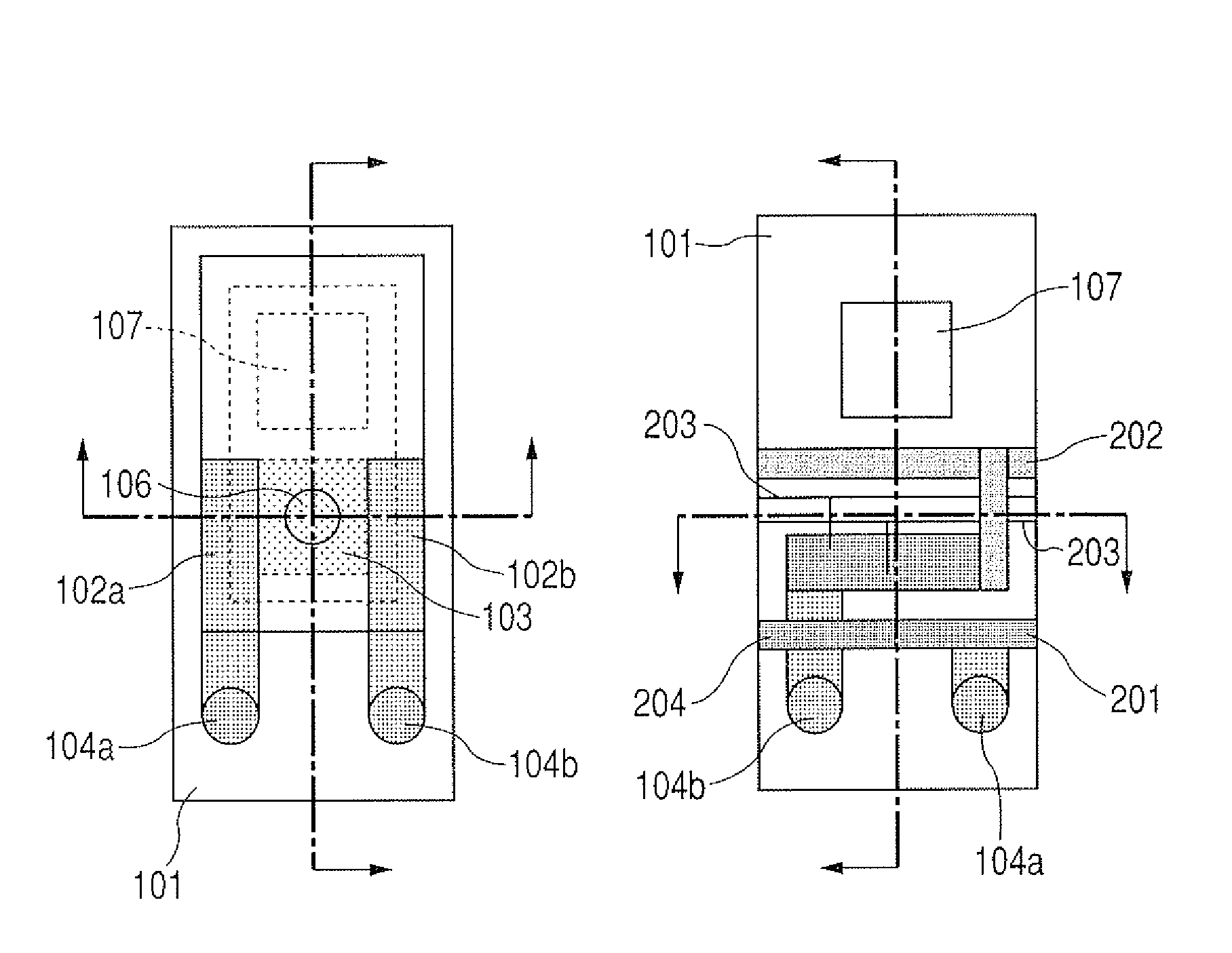
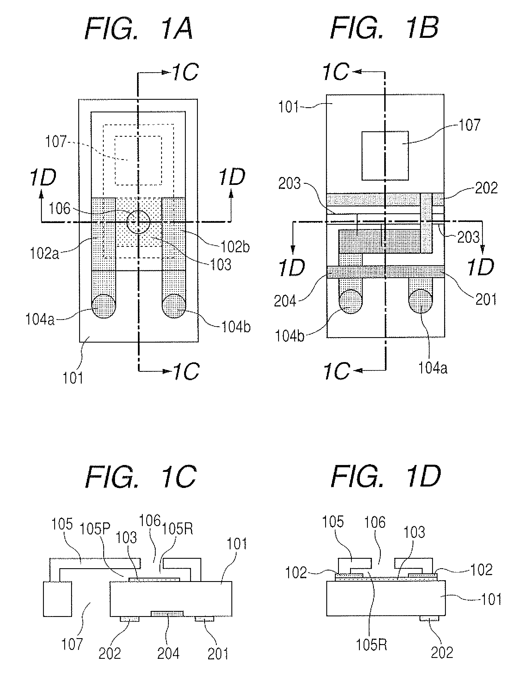
[0020]FIGS. 1A, 1B, 1C and 1D illustrate a completed state of a liquid discharge head according to an embodiment of the present invention. FIG. 1A is a plan view of the liquid discharge head of the present embodiment as viewed from the surface of a head substrate, FIG. 1B is a plan view viewed from the back surface of the head substrate on a side opposite to a side of FIG. 1A, FIG. 1C is a sectional view cut along the 1C-1C line of FIGS. 1A and 1B, and FIG. 1D is a sectional view cut along the 1D-1D line of FIGS. 1A and 1B.

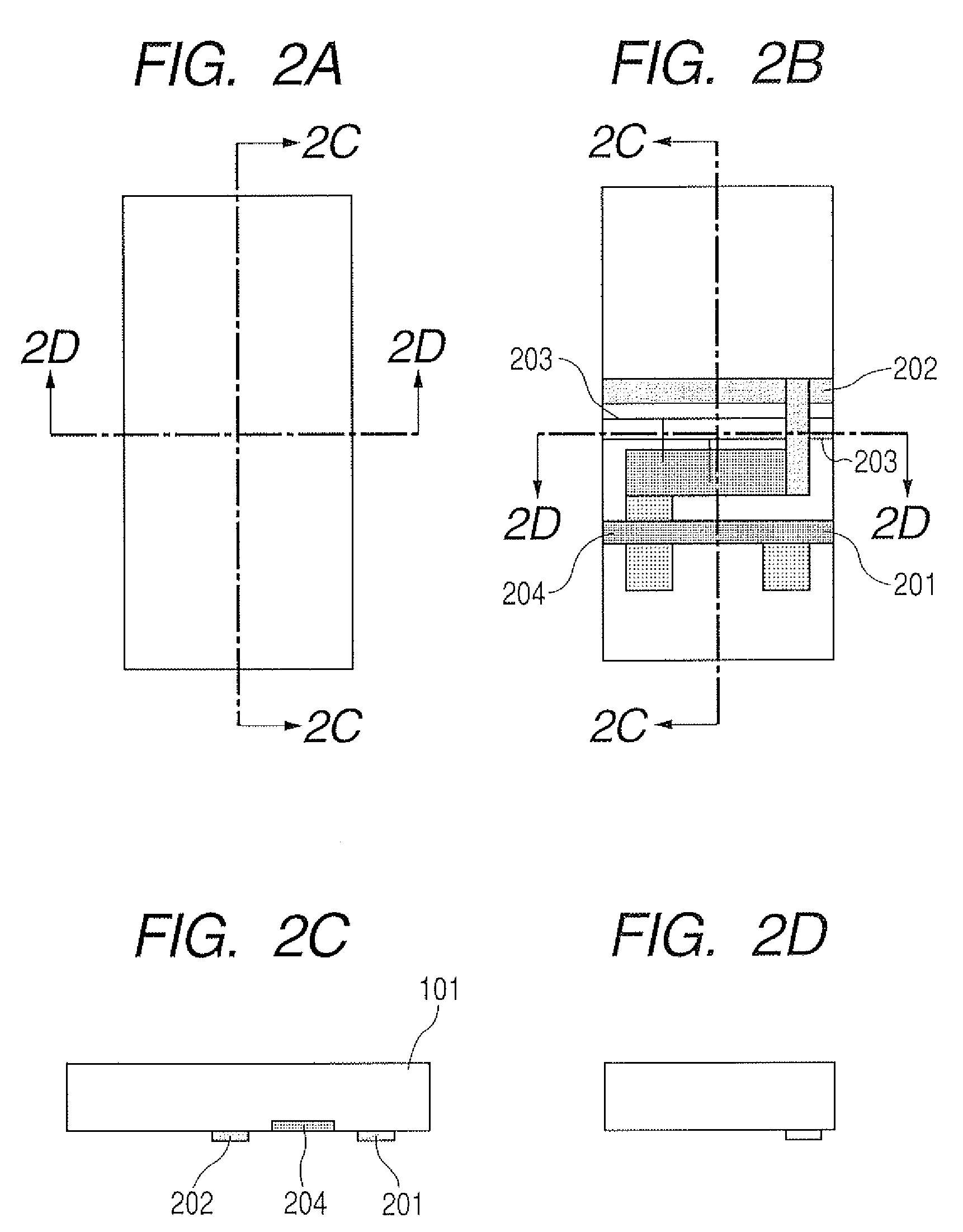
[0021]Moreover, FIGS. 2A to 5D are explanatory views of manufacturing steps of the liquid discharge head according to the present embodiment.

[0022]Here, FIGS. 2A, 3A, 4A and 5A are plan views illustrating a front surface of the head substrate, and FIGS. 2B, 3B, 4B and 5B are plan views illustrating the back surface of the head substrate.

[0023]Furthermore, FIG....


PUM


Abstract

A liquid discharge head includes a substrate having a discharge port, a plurality of energy generating elements disposed on a first surface of the substrate for generating energy to discharge liquid from the discharge port, a liquid supply port, and a member provided on the first surface and forming a wall of a liquid chamber and a wall of a liquid path from the liquid supply port through the liquid chamber to the discharge port. A plurality of first penetrating electrodes penetrate the substrate from the first surface to the second surface, wherein one of the first penetrating electrodes electrically connects one of the energy generating elements, and a plurality of second penetrating electrodes penetrate the substrate from the first surface to the second surface, wherein one of the second penetrating electrodes electrically connects to the same energy generating element connected to the first penetrating electrode. Also, first and second power wirings are provided, and a plurality of driving elements are electrically connected between the first penetrating electrode and the first power wiring, correspondingly to each of the energy generating elements, to drive and control the energy generating elements.

Description

BACKGROUND OF THE INVENTION[0001]1. Field of the Invention[0002]The present invention relates to a liquid discharge head which discharges a liquid.[0003]2. Description of the Related Art[0004]Heretofore, a liquid discharge head has been configured to discharge a liquid in a direction vertical to the surface of the head on which a heating resistor is disposed, and the head has been put to practical use. In such a liquid discharge head, as shown in FIG. 7A, in general, a liquid supply port 302 is rectangular as viewed from an upper surface of a head substrate 301, and liquid discharge ports 303 are linearly arranged as rows of discharge ports on opposite sides of the liquid supply port. It is to be noted that the arranged rows of liquid discharge ports 303 open at a discharge port open surface 305. FIG. 7B is a sectional view cut along the 7B-7B line of FIG. 7A. As shown in the drawing, heating resistors (hereinafter referred to as the heaters) 304 are arranged so as to face the liqui...

Claims


Application Information

Patent Timeline
Patent Type & Authority Patents(United States)
IPC IPC(8): B41J2/05
CPCB41J2/1404B41J2/14072B41J2/145B41J2002/14387
Inventor KOMURO, HIROKAZU
Owner CANON KK
Why Eureka
Try Eureka