
Multigroup-multiphase rotating-electric-machine driving apparatus

a technology of multi-phase rotating and driving apparatus, which is applied in the direction of electric/dynamo-electric converter starters, control systems, dynamo-electric converter control, etc., to achieve the effect of affecting the braking torqu

Active Publication Date: 2021-01-26
MITSUBISHI ELECTRIC CORP
View PDF7 Cites 0 Cited by
  • Summary
  • Abstract
  • Description
  • Claims
  • Application Information

AI Technical Summary

Benefits of technology

The present invention is a rotating electric machine that can prevent overvoltage and reduce fluctuation in braking torque when the connection between the machine and the battery is cut off. This helps to protect the motor control apparatus and other vehicle apparatuses from being broken by the overvoltage.

Problems solved by technology

Such a rapid voltage hike in the DC charging portion of the inverter may cause a trouble such as deterioration or breakage of a circuit element included in the inverter or the control apparatus including the inverter.

Method used


Image

  • Multigroup-multiphase rotating-electric-machine driving apparatus
  • Multigroup-multiphase rotating-electric-machine driving apparatus
  • Multigroup-multiphase rotating-electric-machine driving apparatus

Examples


embodiment 1

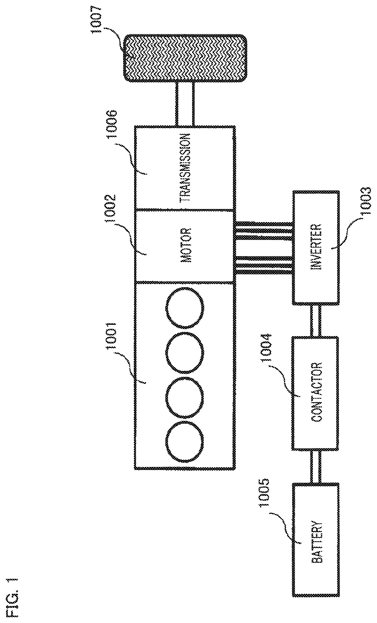
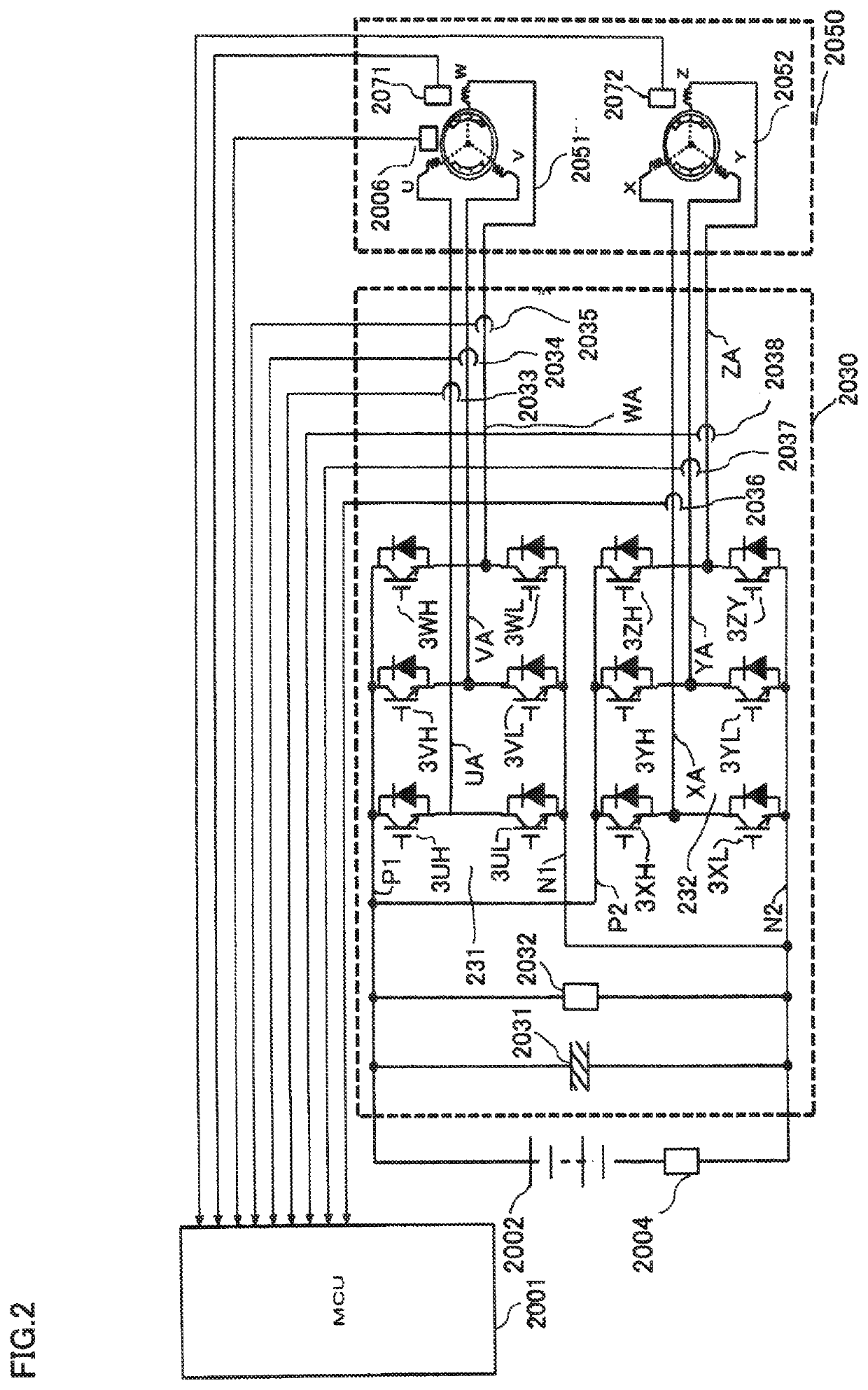
[0040]FIG. 2 is a schematic configuration diagram of a rotating-electric-machine driving apparatus according to any one of Embodiment 1 and after-mentioned Embodiment 2 of the present invention. In FIG. 2, as an example of the rotating-electric-machine driving apparatus according to any one of Embodiments 1 and 2 of the present invention, a motor inverter system having an AC-rotating-electric-machine driving apparatus is represented.

[0041]In FIG. 2, a two-group-three-phase motor 2050 corresponds to the moto 1002 in foregoing FIG. 1 and is a so-called permanent-magnet rotating electric machine that is configured as a motor generator having a power generation function, that has independent two groups of armature windings in the stator, and that has magnetic-field poles formed of permanent magnets in the rotor; however, in the following explanation, the permanent-magnet rotating electric machine will be referred to simply as a two-group-three-phase motor.

[0042]In its stator, the two-gr...

embodiment 2

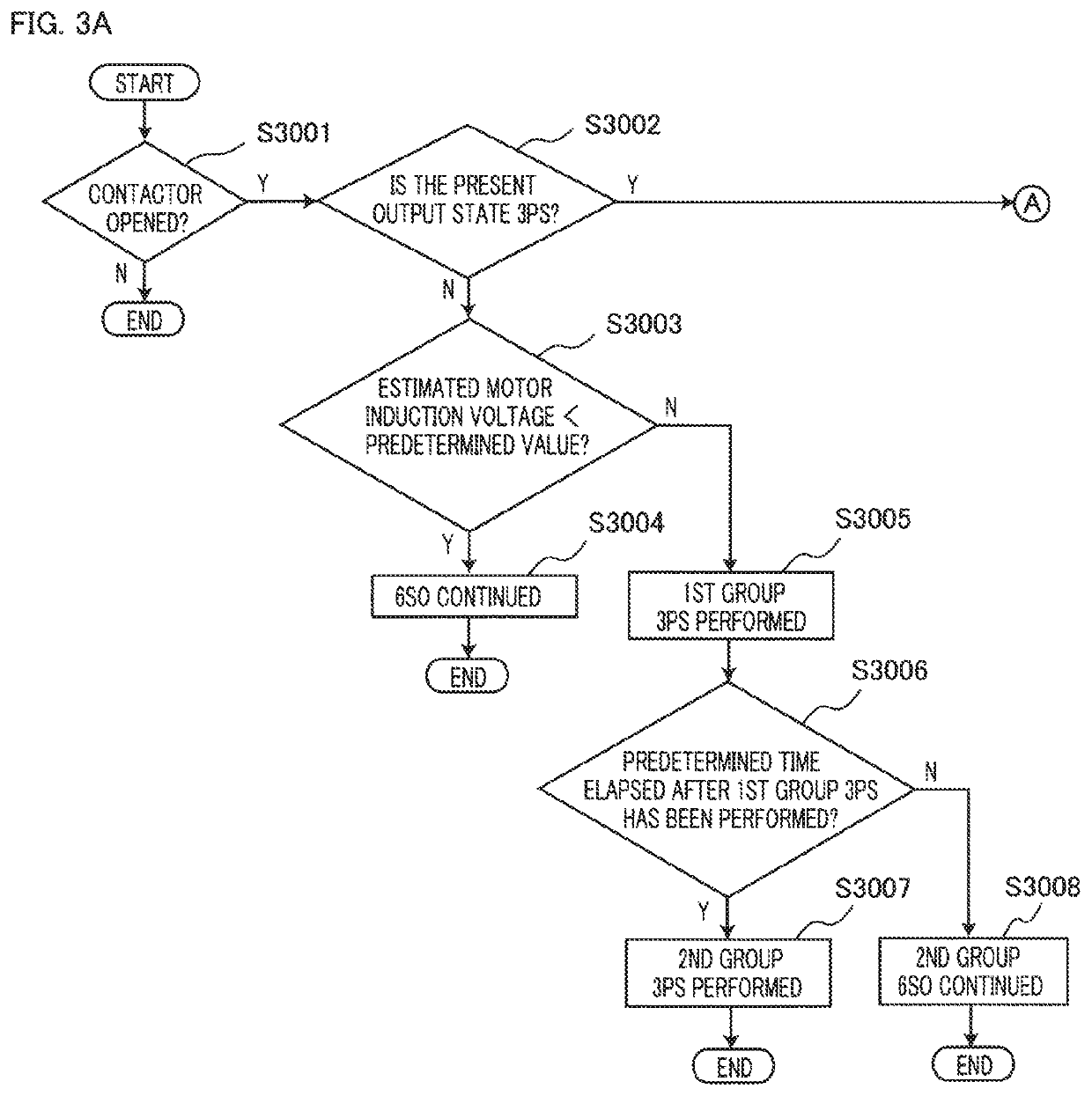
[0112]Next, a rotating-electric-machine driving apparatus according to Embodiment 2 of the present invention will be explained. FIG. 4A and FIG. 4B are flowcharts representing the operation of the rotating-electric-machine driving apparatus according to Embodiment 2 of the present invention. The differences between Embodiment 1 and Embodiment 2 are only the respective differences between the steps S3006, S3007, and S3008 in FIG. 3A and the steps S4006, S4007, and S4008 in FIG. 4A; thus, in the explanation below, the differences will mainly be explained. Hereinafter, by use of FIG. 4A and FIG. 4B, the case where the step S4006 is utilized when the all-phase cutoff (6SO) state is switched to the three-phase short-circuiting (3PS) state will be explained in detail.

[0113]In the step S4006 in FIG. 4A, it is determined whether or not a first-group q-axis current is of a positive value. In the case where when the three-phase short-ciruiting (3PS) is applied to the first group including the...


PUM


Abstract

When the connection between a DC power source and a multigroup-multiphase electric-power conversion apparatus is cut off, a control apparatus controls switching devices so that the respective states of the two or more groups of electric-power conversion apparatuses included in the multigroup-multiphase electric-power conversion apparatus are each switched stepwise from all-phase short-circuiting state to an all-phase cutoff state at different timings.

Description

CROSS REFERENCE TO RELATED APPLICATIONS[0001]This application is a National Stage of International Application No. PCT / JP2017 / 018511 filed May 17, 2017.TECHNICAL FIELD[0002]The present invention relates to a rotating-electric-machine driving apparatus to be mounted in a vehicle or the like and more particularly to a multigroup-multiphase rotating-electric-machine driving apparatus having independent multigroup-multiphase armature windings in a stator and magnetic-field poles formed of permanent magnets in a rotor.BACKGROUND ART[0003]In recent years, as a vehicle in which energy saving and environment are considered, a hybrid vehicle and an electric automobile have been drawing attention. A hybrid vehicle has an electric motor, as a driving power source, in addition to a conventional engine. An electric automobile has only an electric motor, as a driving power source. Each of a hybrid vehicle and an electric automobile makes an inverter convert DC electric power stored in a battery i...

Claims


Application Information

Patent Timeline
Patent Type & Authority Patents(United States)
IPC IPC(8): H02P1/00H02P25/22H02P29/024H02P27/06
CPCH02P25/22H02P27/06H02P29/0241
Inventor WATANABE, MASUTAKAENOKI, KEIICHINISHIJIMA, YOSHIMASAHARADA, SHINGO
Owner MITSUBISHI ELECTRIC CORP
Learn More