System for mounting equipment and structures offshore

a technology for mounting equipment and structures, applied in the direction of artificial islands, floating buildings, bridges, etc., can solve the problem of limiting the movement of the carrier relative to the foundation

Active Publication Date: 2010-03-30
THEY JAN
View PDF21 Cites 18 Cited by
  • Summary
  • Abstract
  • Description
  • Claims
  • Application Information

AI Technical Summary

Benefits of technology

[0014]In still another aspect, some of the connecting elements may be flexible, elongated elements, such as rope, wire, chain or similar elements that only transfer pulling forces. These connecting elements may be pre-tensioned by buoyancy. Other connecting elements may be formed to transfer pushing forces. The use of three connecting elements may stabilize the carrier against possible tilt.
[0027]In another aspect elastic parts may produce the swiveling of the connecting elements relative to the carrier or the foundation. This is possible because the relative movement of the carrier, connecting elements and foundation may only be a few degrees. The use of pillars with special profiles can be successful.

Problems solved by technology

The carrier is connected to the foundation by two or more connecting elements, which limit possible motion of the carrier relative to the foundation.

Method used


Image

  • System for mounting equipment and structures offshore
  • System for mounting equipment and structures offshore
  • System for mounting equipment and structures offshore

Examples


Embodiment Construction

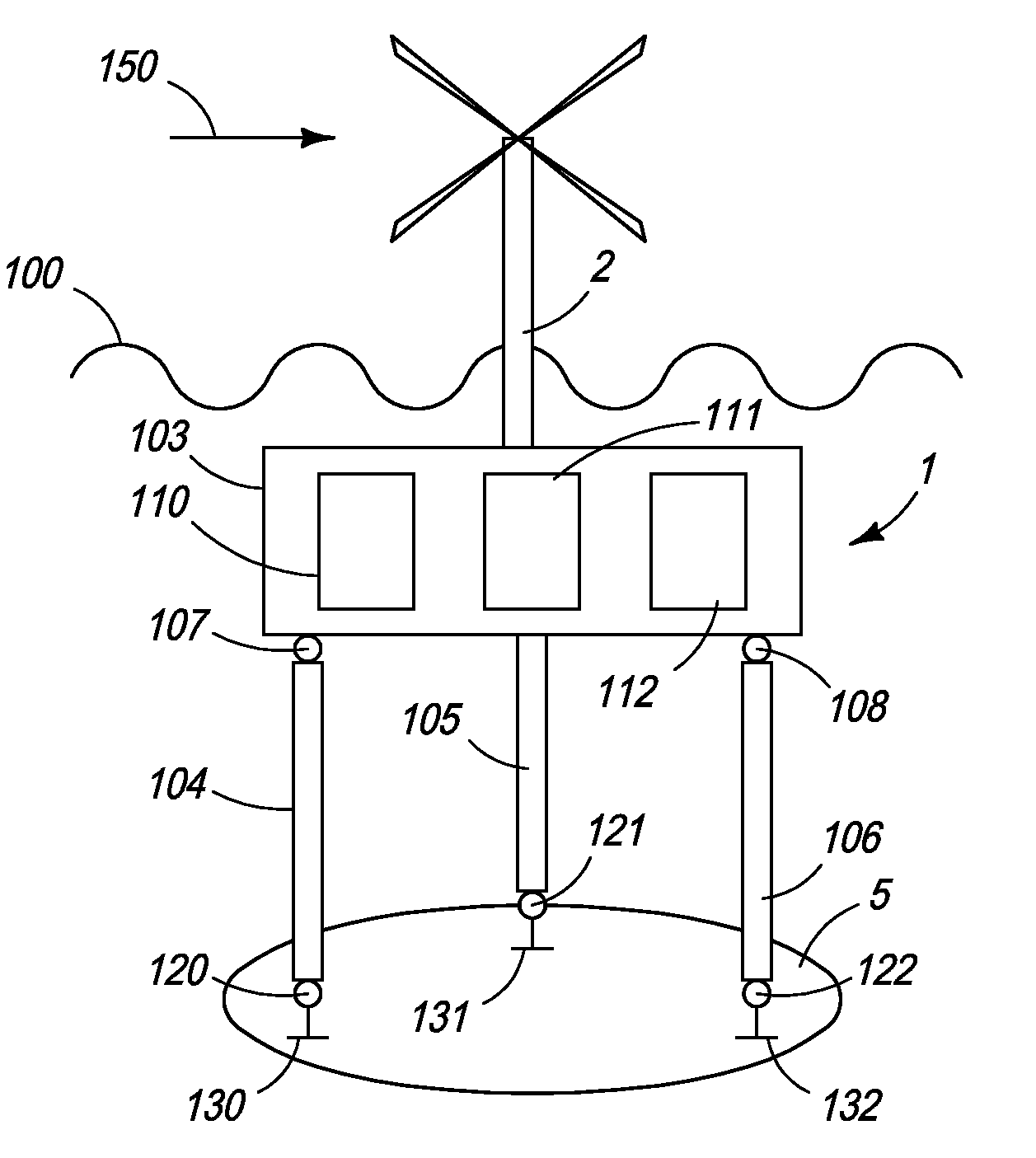
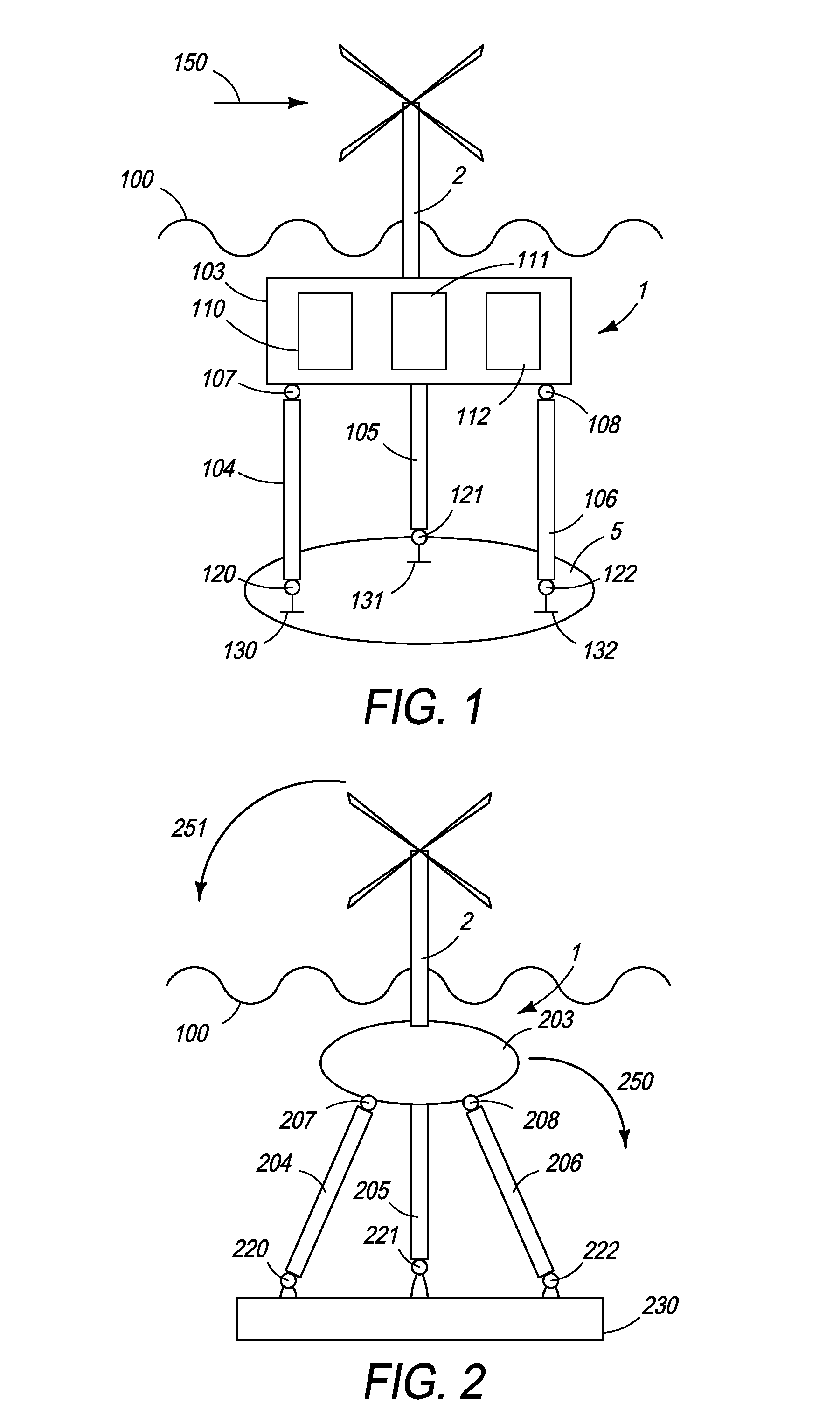
[0038]Referring to FIG. 1, a schematic drawing of exemplary mounting system 1 in which the principles of the present invention may be advantageously practiced is illustrated generally. The exemplary system carries structure 2, which is illustrated as a wind-electric generator. Structure 2 is securely attached to carrier 103. Carrier 103 is attached to connecting elements 104, 105, and 106. Connecting elements 104, 105, and 106 are attached to foundation 5, here being the sea bed. Any other stable structure may be used as a foundation. Suitable alternative foundation structures are discussed below.

[0039]The connecting elements 104, 105, and 106 are pivotably joined to carrier 103 and foundation 5, preferably with carrier joints 107 and 108 and anchor joints 120, 121, and 122. Connecting elements 104, 105, and 106 limit motion of carrier 103 along each connecting elements' longitudinal axis. Depending on the number and orientation of the connecting elements 104, 105, and 106 the motio...


PUM


Abstract

A mounting system is disclosed for mounting structures and equipment, such as wind-electric generators on water. The structure is attached to a carrier, which is attached to a foundation through connecting elements. Buoyancy tanks or the inherent buoyancy of the carrier or the connecting elements are used to maintain a stable position of the carrier in the water. Utilizing connecting elements that transfer pushing and pulling forces, undesirable movements of the carrier are suppressed while requiring only moderate forces on the foundation.

Description

CLAIM FOR PRIORITY[0001]This application claims priority to German application number DE102006033215.6, which was filed in the German language on Jul. 13, 2006 and which is hereby incorporated by reference.TECHNICAL FIELD[0002]The present invention generally relates to a system and method for mounting equipment and structures offshore, and more particularly, to a system and method for mounting high rising equipment and structures on a floating carrier that is attached to a foundation through connecting elements.BACKGROUND OF THE INVENTION[0003]Wind-electric generators provide a clean and renewable source of electric energy. Mounting wind-electric generators offshore is particularly attractive, as winds offshore are often stronger and steadier than on land. Further, offshore structures often face less resistance by neighbors afraid of noise pollution or the appearance of high rising structures in general. However, wind-electric generators experience strong forces acting on their roto...

Claims


Application Information

Patent Timeline
Patent Type & Authority Patents(United States)
IPC IPC(8): B63B21/50
CPCB63B21/50B63B35/44E01D15/14E01D19/02F03D11/045B63B1/04B63B1/107B63B21/502B63B2001/044B63B2035/446E02B2017/0091F05B2240/93Y02E10/727F03D13/22F03D13/25Y02E10/72
Inventor THEY, JAN
Owner THEY JAN
Why Eureka
Try Eureka