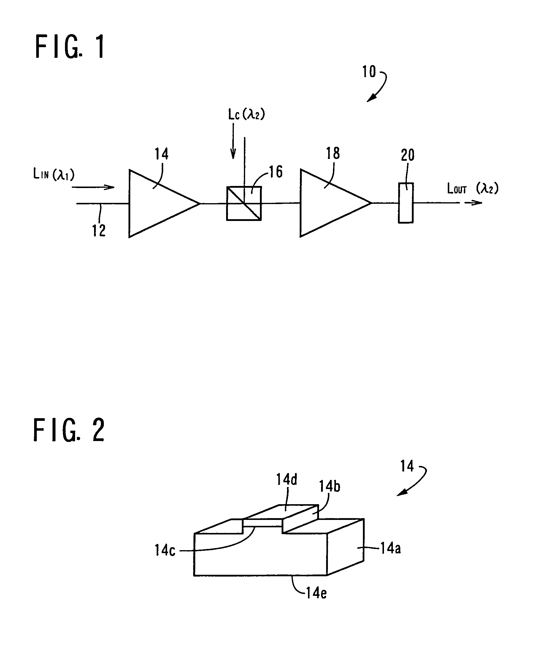
[0021]There is provided according to a first aspect of the invention a three-terminal optical signal amplifying device being characterized by comprising: (a) a first semiconductor optical amplifying element and a second semiconductor optical amplifying element, each of the semiconductor optical amplifying element being respectively provided with an active layer constituted by a p-n junction; (b) a first input means to input a first input light at a first wavelength to the first semiconductor optical amplifying element; (c) a first wavelength selecting element which selects the total or a portion of a predetermined width of a wavelength band of a neighboring light at other wavelength than the first wavelength, from a light which is output from the first semiconductor optical amplifying element; (d) a second input means to input a second input light at a second wavelength to the second semiconductor optical amplifying element, together with the total or the portion of the predetermined width of the wavelength band of the neighboring light at other wavelength than the first wavelength which is selected by the first wavelength selecting element; and (e) a second wavelength selecting element which selects a light at the second wavelength, from a light which is output from the second semiconductor optical amplifying element. Accordingly, the selected light in a certain wavelength band of the neighboring light at other wavelength than the first wavelength which is selected from the output light from the first semiconductor optical amplifying element and input to the second semiconductor optical amplifying element, has a reversed intensity to that of the output signal light at the first wavelength, and furthermore, has a sufficient intensity even when a bias light does not provided from a laser source. Consequently, in the second semiconductor optical amplifying element, cross gain modulation is generated and sufficient optical signal amplification is obtained due to the second input light (control light) at the second wavelength. In the three-terminal optical signal amplifying device according to the first aspect of the invention, a little changes in the temperature is expected and consequently, steady, constant operations are expected because no input of the bias light (laser light) which is the second input light at the second wavelength into the first semiconductor optical amplifying element in a predetermined intensity is required. Further, in the three-terminal optical signal amplifying device according to the first aspect of the invention, the first input light at the first wavelength is an input light which is intensity-modulated, the second input light at the second wavelength is a control light, and an output light at the second wavelength is provided with a signal waveform which the first input light is intensity-modulated during the control light is input. Accordingly, the output light with a wavelength in accordance with on / off or the intensity modulation can be obtained.
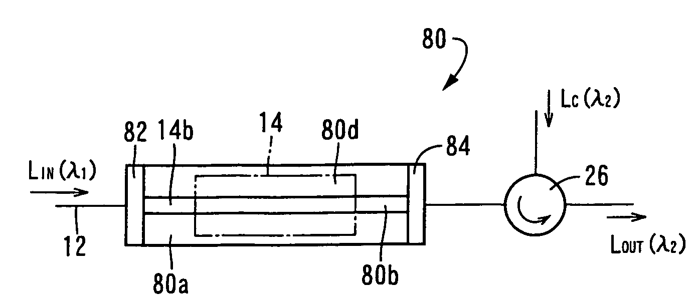
[0022]There is provided according to a second aspect of the invention a three-terminal optical signal amplifying device being characterized by comprising: (a) a first semiconductor optical amplifying element being provided with an active layer constituted by a p-n junction; (b) a first input means and a second input means to respectively input a first input light at a first wavelength and a second input light at a second wavelength to an end face side and another end face side of the first semiconductor optical amplifying element, respectively; (c) a third wavelength selecting element which is provided on the end face side of the first semiconductor optical amplifying element, which permits the first input light at the first wavelength which is input from the first input means to pass through, and which reflects a light at the second wavelength in a light which is input from the first semiconductor optical amplifying element, so that the light at the second wavelength is input to the first semiconductor optical amplifying element; and (d) a fourth wavelength selecting element which is provided on the another end face side of the first semiconductor optical amplifying element, which permits the second input light at the second wavelength which is input from the second input means to pass through, and which reflects a light at the first wavelength in a light which is input from the first semiconductor optical amplifying element, so that the light at the first wavelength is input to the first semiconductor optical amplifying element, (e) wherein the first input light at the first wavelength is an input light which is intensity-modulated; wherein the second input light at the second wavelength is a control light; and wherein an output light at the second wavelength is selected by the fourth wavelength selecting element and output, and is provided with a signal waveform which the first input light is intensity-modulated during the control light is input. Accordingly, the phase of the output light is the inverse phase of the first input light, and the wavelength is converted from the first wavelength to the second wavelength. The cross gain modulation occurs in the first semiconductor optical amplifying element and the optical signal amplification is provided by the second input light (control light) at the second wavelength. Using only one amplifying element, that is, the first semiconductor optical amplifying element, causes simplicity in its structure and, consequently, facility of manufacturing. The first input light at the first wavelength is an input light modulated in intensity, and the control light (second input light) at the second wavelength is a control light changed in intensity. FIG. 17 shows the output light at the second wavelength that has a signal waveform which the first input light is intensity-modulated during the control light is input. Consequently, the three-terminal optical signal amplifying device according to the second aspect of the invention can output the output light which is modulated in intensity, in accordance with an input of the control light.
[0023]There is provided according to a third aspect of the invention the device defined in the first aspect of the invention, wherein the second wavelength of the second input light used, for example, as the control light is equal to the first wavelength. Consequently, input and output signals having the single wavelength causes the simple construction of the optical circuitry
[0024]There is provided according to a fourth aspect of the invention the device defined in any one of the first to third aspect of the invention, wherein a gain of the output light at the second wavelength with respect to the second input light (control light) at the second wavelength is not smaller than 10. Accordingly, a sufficient gain is obtained.
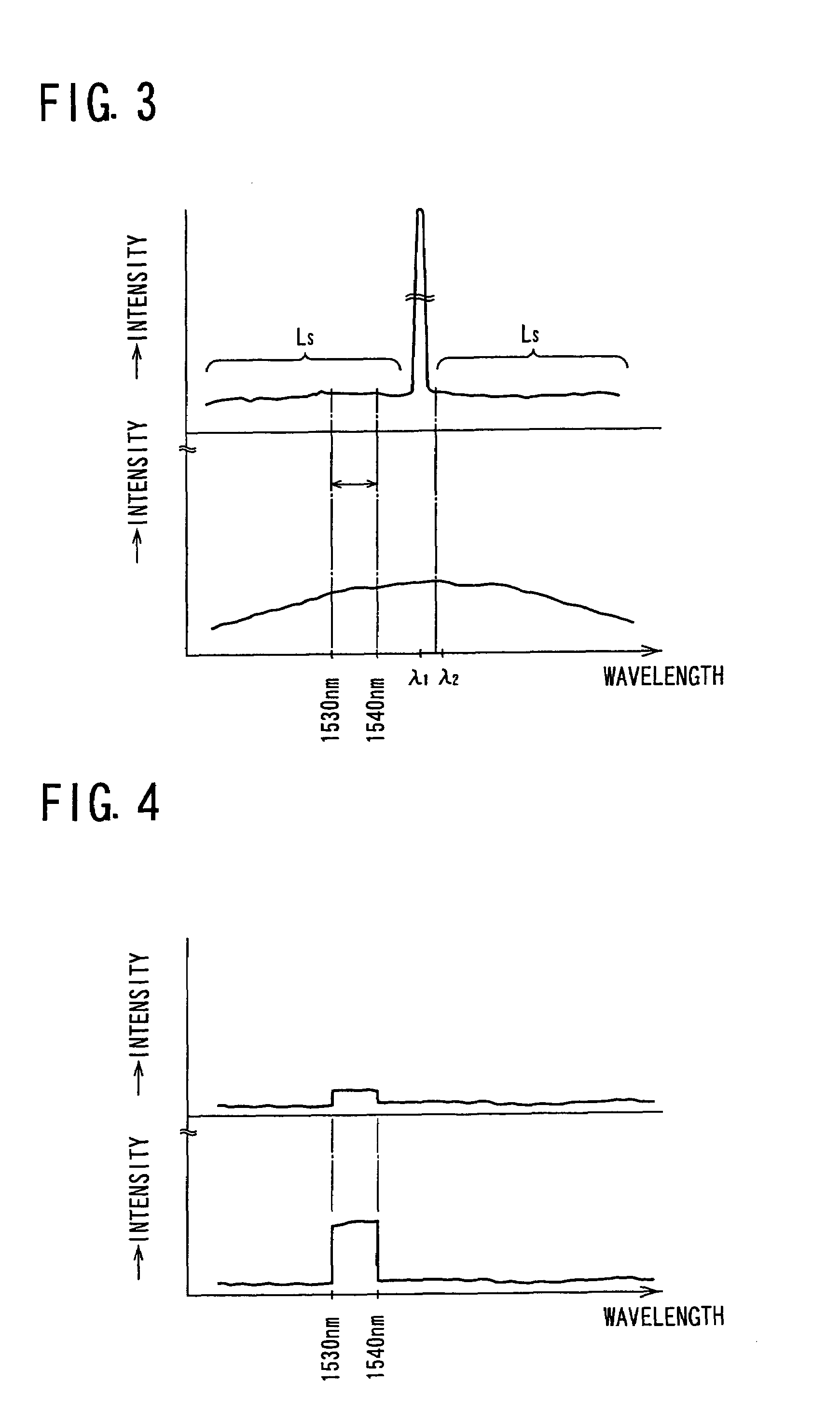
[0025]There is provided according to a fifth aspect of the invention the device defined in any one of the first, third and fourth aspect of the invention, wherein the first wavelength selecting element and / or the second wavelength selecting element is a wavelength selecting filter which selects a light of which a spectrum range extends over not less than 5 nm. Consequently, the neighboring light having a sufficient signal intensity can be input to the second semiconductor optical amplifying element.
[0026]There is provided according to a sixth aspect of the invention the device defined in any one of the first to fifth aspect of the invention, wherein the first wavelength selecting element, the second wavelength selecting element, the third wavelength selecting element and / or the fourth wavelength selecting element is constituted by one of a grating filter and a multilayer filter, the grating filter being formed such that a portion of the grating filter is effected to have a periodical change in the refractive index, and the multilayer filter being formed so that a plurality of pairs of layers that have different refractive indices from each other are laminated in the multilayer filter. This causes facility for manufacturing and providing with an integrated device operating as a one-chip device.

