Automatic pool cleaner

Active Publication Date: 2010-04-06
ZODIAC POOL SYST LLC
View PDF68 Cites 62 Cited by
  • Summary
  • Abstract
  • Description
  • Claims
  • Application Information

AI Technical Summary

Benefits of technology

[0007]In accordance with the invention, an automatic pool cleaner is provided of the type for random travel over submerged floor and side wall surfaces of a swimming pool or the like to dislodge and collect debris. The pool cleaner includes an electric-powered traction drive system for rotatably driving cleaner wheels, and an electric-powered water management system including a water supply pump and related manifold unit for venturi-vacuuming and collection of settled debris within a porous filter bag. A directional control system including an on-board compass monitors turning movements of the pool cleaner during normal random travel operation, and functions to regulate the traction drive system in a manner to prevent, e.g., excess twisting of a conduit such as a power cable tethered to the pool cleaner.
[0010]The electric-powered water supply pump is also mounted on the internal support frame within the cleaner housing. This water supply pump includes a rotary-driven impeller for drawing in a supply of water and for delivering that water under pressure to a manifold unit. The manifold unit includes a plenum or pressure chamber communicating with an annular jet nozzle ring, or alternately with at least one and preferably multiple jet nozzles, disposed generally at a lower end of a pool cleaner suction mast and aimed upwardly to induce by venturi action an upwardly directed suction flow of water therethrough into a filter bag mounted at an upper end of the suction mast. An open lower end of the suction mast is defined by the cleaner housing in close proximity with an underlying pool surface, whereby this upwardly directed suction flow effectively vacuums settled debris from the underlying pool surface into the filter bag.

Problems solved by technology

Although such filtration systems function efficiently to collect suspended particulate, it has been recognized that some particulate tends to settle onto submerged pool floor and wall surfaces and thus is not removed by the standard filtration system.

Method used


Image

  • Automatic pool cleaner
  • Automatic pool cleaner
  • Automatic pool cleaner

Examples


Embodiment Construction

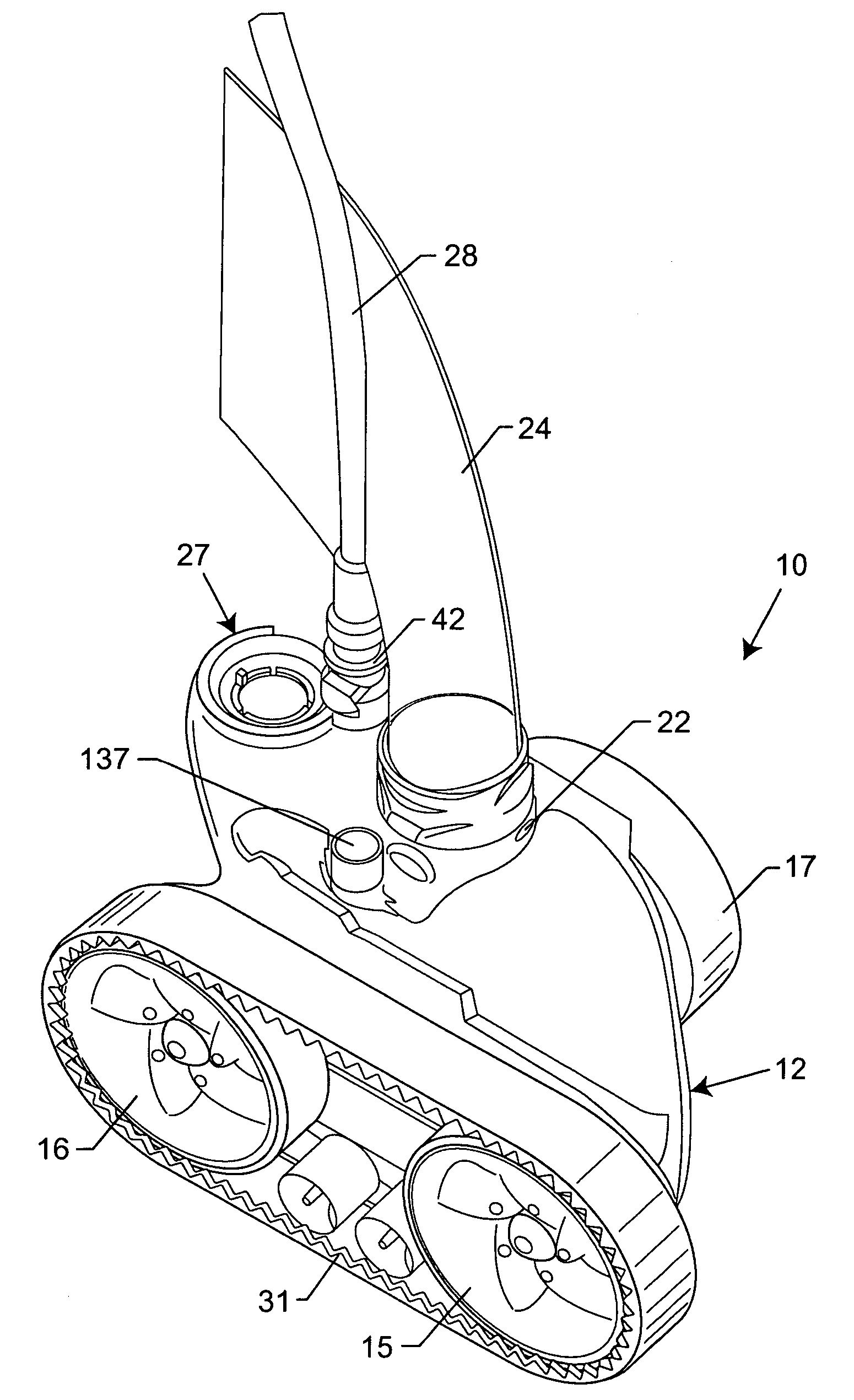
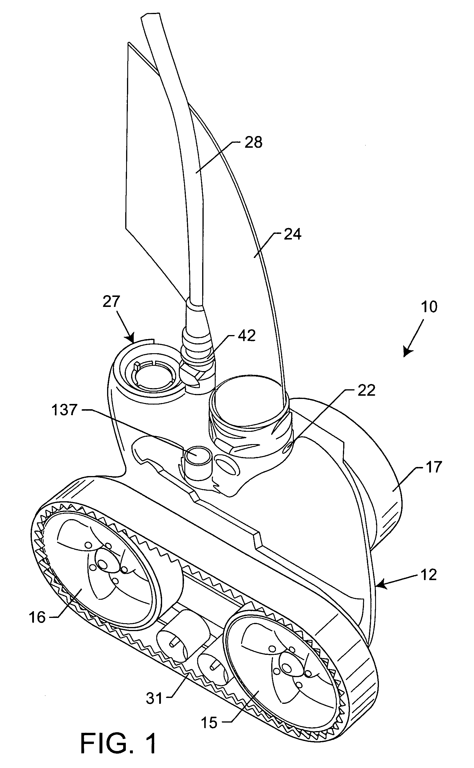
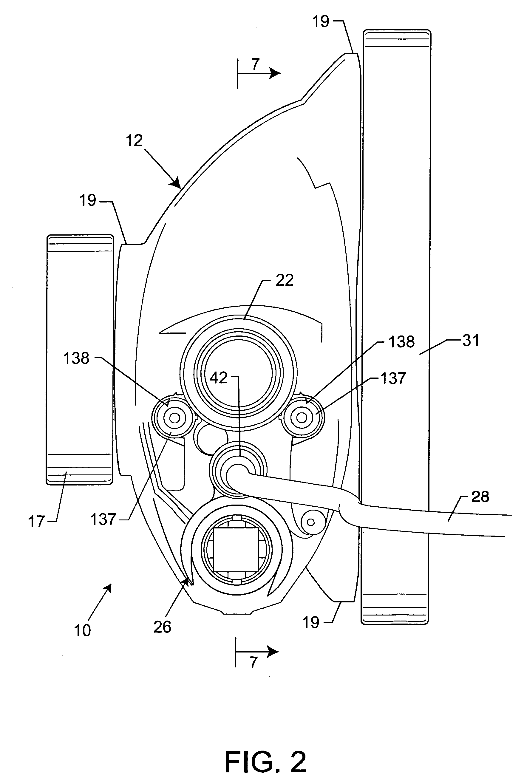
[0048]As shown in the exemplary drawings, an improved automatic pool cleaner referred to generally by the reference numeral 10 is provided for travel over submerged floor and side wall surfaces within a swimming pool or the like to dislodge and / or collect debris and sediment. As viewed generally in FIGS. 1-3, the improved pool cleaner 10 comprises an hydraulically contoured or streamlined external housing 12 supported by a plurality of rotatably driven wheels 15, 16 and 17 for travel within the swimming pool or the like. The cleaner housing 12 encases an electric-powered traction drive system 18 (FIGS. 7 and 10-13) for rotatably driving the wheels, and an electric-powered water supply pump 20 (FIGS. 7 and 17-22) for coupling a supply of water under pressure to a suction mast 22 for venturi-action vacuuming of dirt and debris upwardly into a filter bag 24 (FIG. 1). In addition, the improved pool cleaner 10 includes a directional control system 26 (FIGS. 4 and 14-16) including an on-b...


PUM


Abstract

An automatic pool cleaner is provided of the type for random travel over submerged floor and side wall surfaces of a swimming pool or the like to dislodge and collect debris. The pool cleaner includes an electric-powered traction drive system for rotatably driving cleaner wheels, and an electric-powered water management system including a water supply pump and related manifold unit for venturi-vacuuming and collection of settled debris within a porous filter bag. A directional control system including an on-board compass monitors turning movements of the pool cleaner during normal random travel operation, and functions to regulate the traction drive system in a manner to prevent, e.g., excess twisting of a conduit such as a power cable tethered to the pool cleaner.

Description

BACKGROUND OF THE INVENTION[0001]This invention relates generally to pool cleaner devices for dislodging and / or collecting debris within swimming pools and the like. More particularly, this invention relates to an improved pool cleaner of the type designed for generally random travel along submerged floor and side wall surfaces of a swimming pool to dislodge and collect fine sediment and other particulate debris accumulated thereon. The improved pool cleaner is adapted for electric powered operation, and / or includes a directional control system for monitoring cleaner movements in a manner to prevent, e.g., excess twisting of a conduit such as a power cable to which the pool cleaner is tethered.[0002]Automatic swimming pool cleaners are well known in the art for use in maintaining a swimming pool in an overall state of cleanliness. In this regard, residential and commercial swimming pools normally include a standard water filtration system including a main circulation pump and relate...

Claims


Application Information

Patent Timeline
Patent Type & Authority Patents(United States)
IPC IPC(8): E04H4/16
CPCE04H4/1636
Inventor STOLTZ, GERHARD J.BLOCH, KENNETH A.HARMON, ALAN L.PIBURN, JOHN D.SANTOS, CARLO M. S.BERGSTROM, NEIL R.
Owner ZODIAC POOL SYST LLC
Why Eureka
Try Eureka