Gas turbine engine including apparatus to transfer power between multiple shafts

Active Publication Date: 2010-04-06
PRATT & WHITNEY CANADA CORP
View PDF34 Cites 15 Cited by
  • Summary
  • Abstract
  • Description
  • Claims
  • Application Information

AI Technical Summary

Problems solved by technology

All these requirements generally lead to various design compromises so that the engines can deliver a good performance at all times. As with all optimization, however, at some points during an engine cycle, one portion of an engine may be capable of generating more power than is required with reference to the selected operating point of one or more portions of the engine.

Method used


Image

  • Gas turbine engine including apparatus to transfer power between multiple shafts
  • Gas turbine engine including apparatus to transfer power between multiple shafts
  • Gas turbine engine including apparatus to transfer power between multiple shafts

Examples


Embodiment Construction

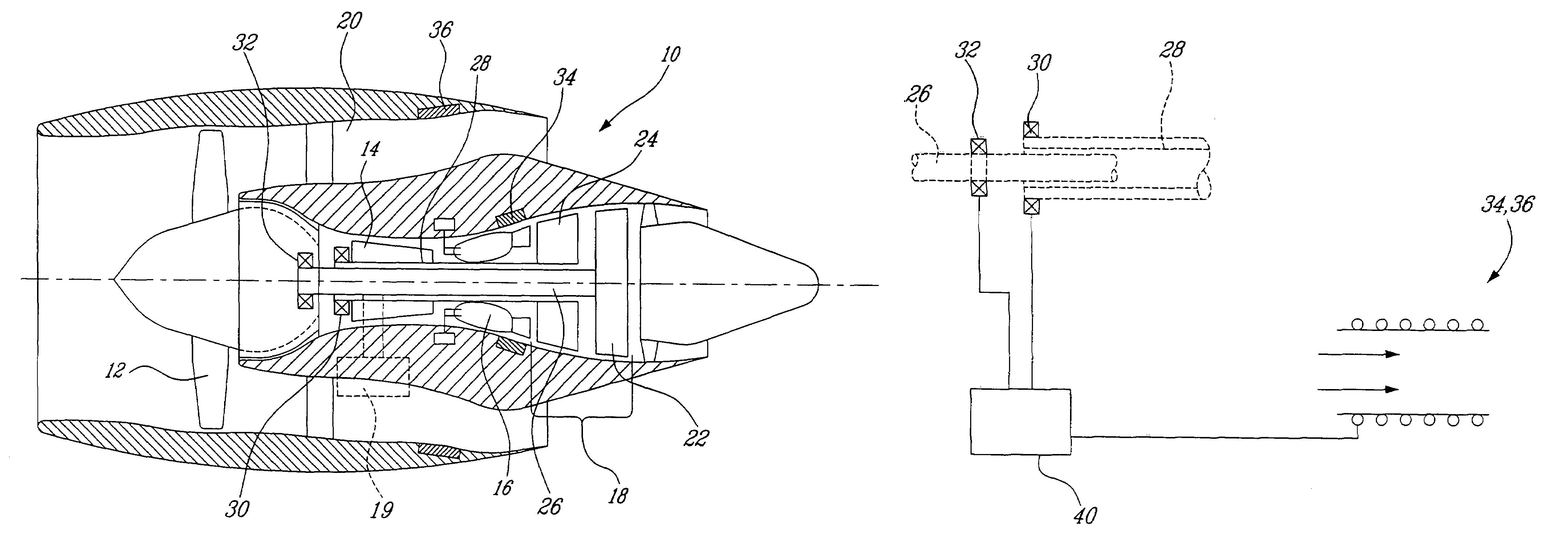
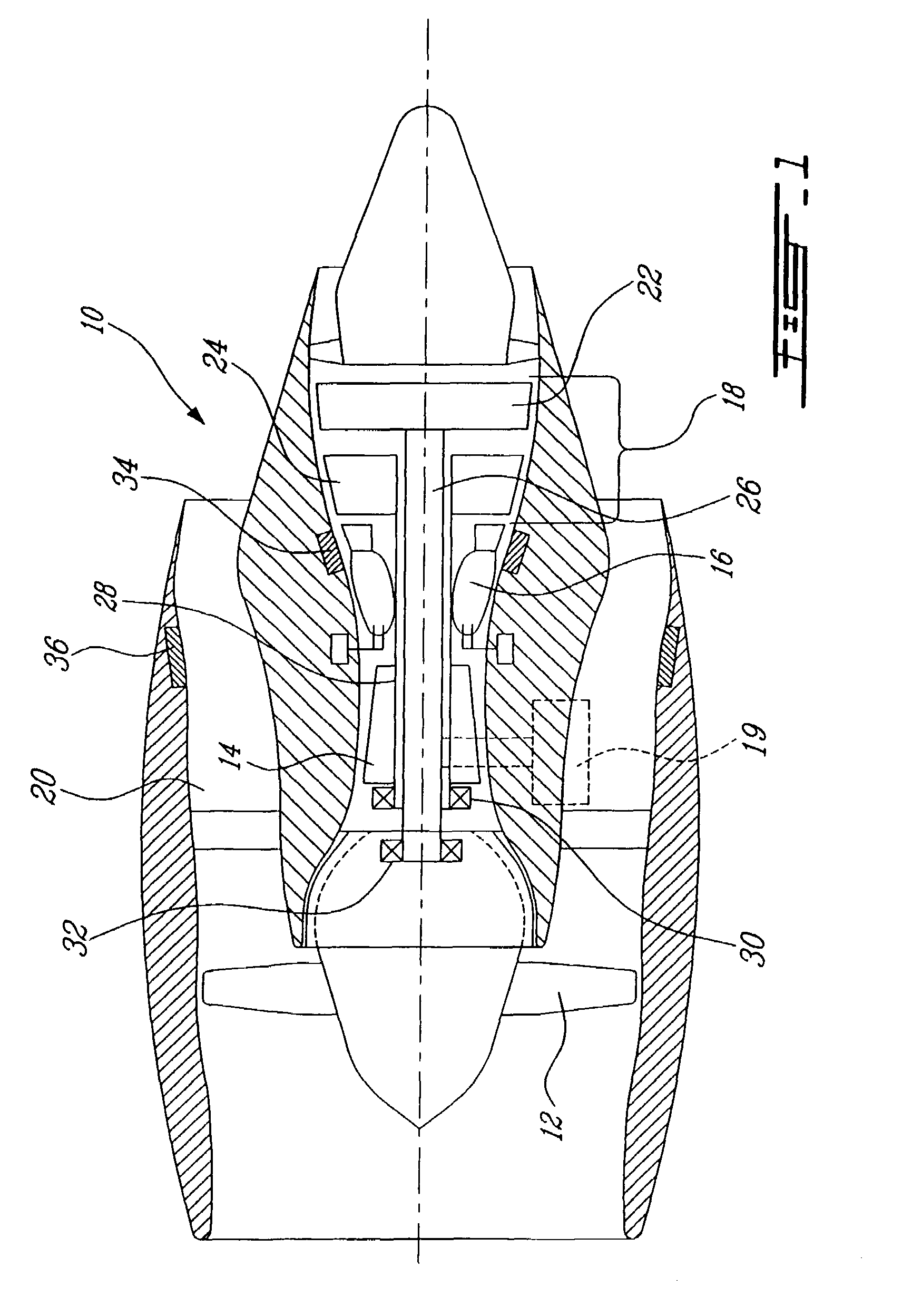
[0018]FIG. 1 illustrates an example of a gas turbine engine 10 of a type preferably provided for use in subsonic flight, generally comprising in serial flow communication a fan 12 through which ambient air is propelled, a multistage compressor 14 for pressurizing the air, a combustor 16 in which the compressed air is mixed with fuel and ignited for generating an annular stream of hot combustion gases, and a turbine section 18 for extracting energy from the combustion gases.

[0019]Gases flowing through the turbine section 18 follow what is referred to hereafter as the core gas path. Some of the air drawn by the fan 12 is sent to a by-pass passage 20 provided around the core of the engine 10, thereby defining the by-pass gas path. It should be noted that the expression “gas path” used herein refers either to the core gas path or the by-pass gas path.

[0020]In a multi-spool engine, the fan 12 is driven by a turbine, namely the low pressure (LP) turbine 22, via a shaft 26 (sometimes calle...


PUM


Abstract

The gas turbine engine comprises at least one electrical generator and an electrical heater associated with a gas path of the engine. The heater is powered by the generator to selectively add heat to the gas turbine cycle.

Description

TECHNICAL FIELD[0001]The invention relates generally to gas turbine engines, and more particularly, to their construction and operation.BACKGROUND OF THE ART[0002]Gas turbine engines, especially those mounted on aircrafts, are known to operate under a wide range of conditions and power requirements. In a typical cycle, a gas turbine engine rotates at high speeds during takeoff and climb segments, while running at lower speeds during other segments, such as warm-up, taxiing, cruise and descent. Gas turbine engines must also operate under various temperatures, pressure and air speeds throughout a same engine cycle. All these requirements generally lead to various design compromises so that the engines can deliver a good performance at all times. As with all optimization, however, at some points during an engine cycle, one portion of an engine may be capable of generating more power than is required with reference to the selected operating point of one or more portions of the engine. I...

Claims


Application Information

Patent Timeline
Patent Type & Authority Patents(United States)
IPC IPC(8): F02G1/00F03H99/00
CPCF01D15/10F02K3/115F02K3/06F02C1/04Y02T50/60
Inventor DOOLEY, KEVIN ALLEN
Owner PRATT & WHITNEY CANADA CORP
Why Eureka
Try Eureka