Method for measuring surface currents using a long-range single station high frequency ground wave radar system

a high-frequency ground wave and radar system technology, applied in the field of surface currents, can solve the problem that the barrick method is only useful

Inactive Publication Date: 2010-04-06
HICKEY KENNETH J
View PDF7 Cites 6 Cited by
  • Summary
  • Abstract
  • Description
  • Claims
  • Application Information

AI Technical Summary

Benefits of technology

[0016]Yet a further object of the present invention is to provide for measuring ocean surface currents using a long-range single station high frequency ground wave radar system that eliminates zones of non-uniform surface current flow.
[0017]An additional object of the present invention is to provide a for measuring ocean surface currents using a long-range single station high frequency ground wave radar system that eliminates zones of non-uniform surface current flow by employing equation of continuity.

Problems solved by technology

However, due to the cost and complexity of two-radar installations, efforts have been made to map surface currents utilizing a single radar.
However, Barrick (1990) proved that this method works only when flow direction is known with respect to the radar beam.
However, it is believed that Barrick's method is only useful in regions where there are known Eddie currents.
Furthermore, both May et al. and Barrick use complex mathematical equations to map surface currents and are limited to short-range system, approximately 50 kilometer range from the radar site.

Method used


Image

  • Method for measuring surface currents using a long-range single station high frequency ground wave radar system
  • Method for measuring surface currents using a long-range single station high frequency ground wave radar system
  • Method for measuring surface currents using a long-range single station high frequency ground wave radar system

Examples


Embodiment Construction

[0026]Prior to proceeding to the more detailed description of the present invention, it should be noted that, for the sake of clarity and understanding, identical components which have identical functions have been identified with identical reference numerals throughout the several views illustrated in the drawing figures.

[0027]It is to be understood that the definition of surface currents applies to surface currents comprising the upper region of the ocean surface of about one meter in height.

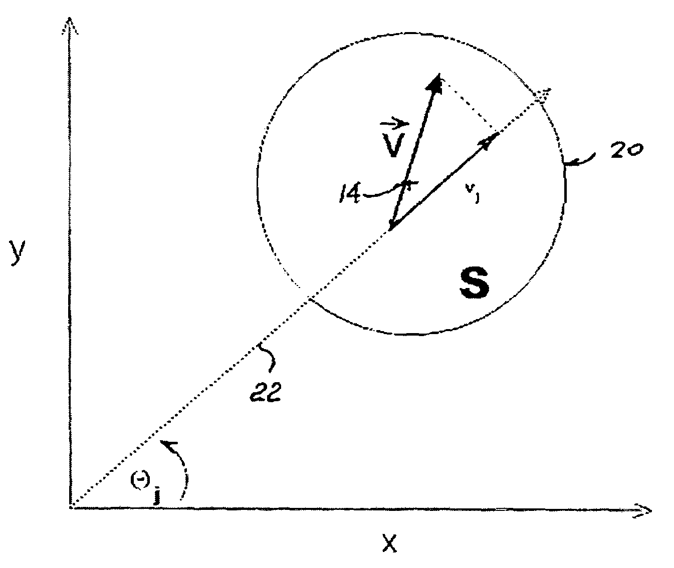
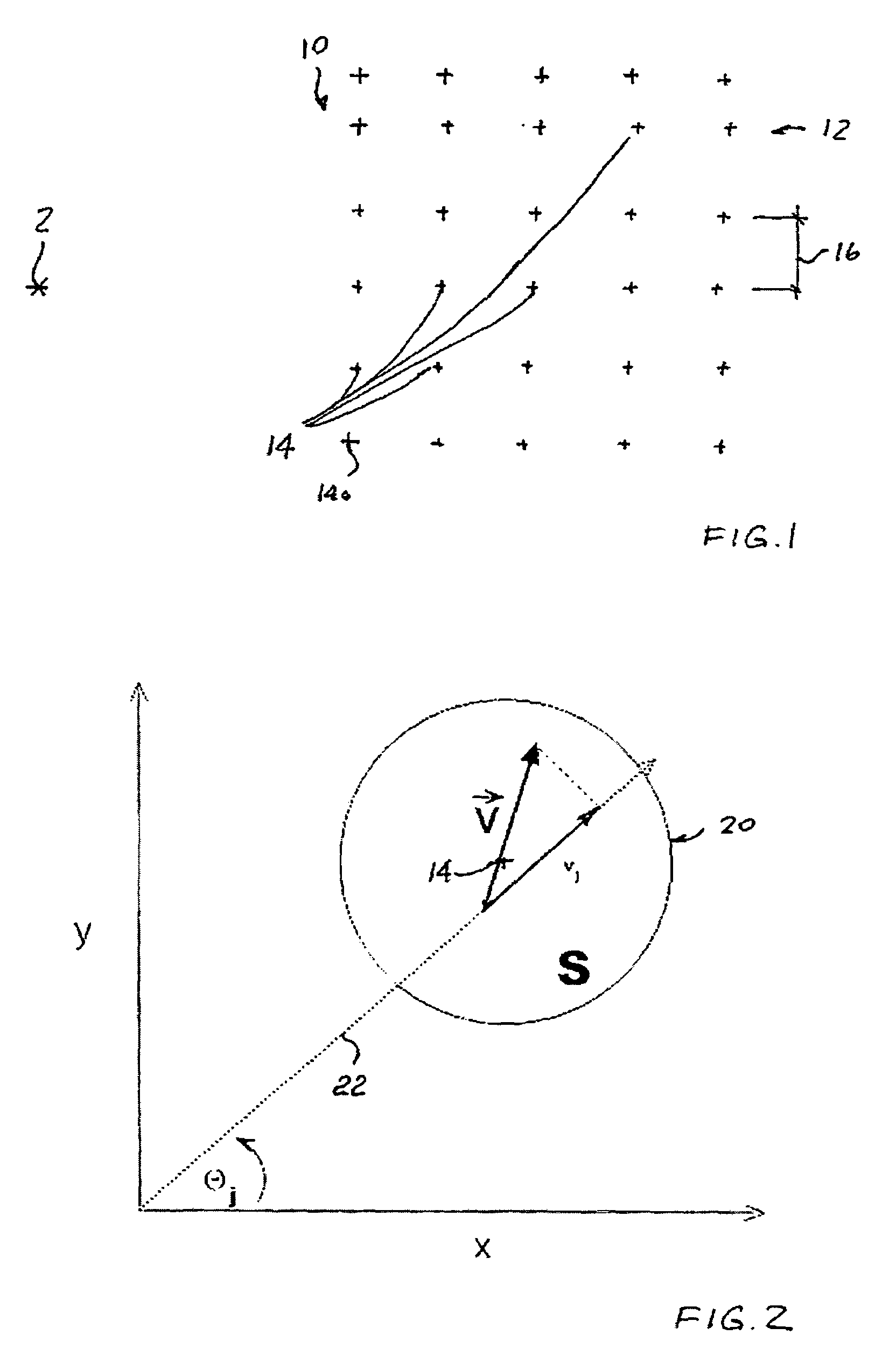
[0028]The present invention provides for measuring ocean surface currents using a long-range single station high frequency ground wave radar system.

[0029]The best mode for carrying out the invention is presented in terms of its presently preferred forms, herein depicted within FIGS. 1 through 7. However, the invention is not limited to the described embodiments, and a person skilled in the art will appreciate that many other embodiments of the invention are possible without deviating from the ...


PUM


Abstract

A method for measuring ocean surface currents using a long-range single station high frequency ground wave radar system includes the steps of forming a rectilinear grid based region, dividing the rectilinear grid into a plurality of sub-regions each having a uniform surface current flow therewithin, spanning each sub-region with a predetermined plurality of radial beam lines from the single radar station, dividing each radial beam line into a pre-selected plurality of radial sub-nodes, measuring radial surface current vector projection at each radial sub-node, inputting each radial surface current vector projection into a multiple regression model having two regressors, determining, with the multiple regression model, surface vector components along each of x and y axis, storing the surface vector components determined in step (g) to a database, and editing, with equation of continuity based algorithm, plurality of surface vector components stored in the database.

Description

CROSS-REFERENCE TO RELATED APPLICATIONS[0001]This application is related to and claims priority from Provisional Patent Application Ser. No. 60 / 965,070 filed on Aug. 17, 2007.FIELD OF THE INVENTION[0002]The present invention relates, in general, to surface currents and, more particularly, this invention relates to a method for measuring ocean surface currents using a long-range single station high frequency ground wave radar system.BACKGROUND OF THE INVENTION[0003]As is generally well known, conventional practice of mapping surface currents, which transport floating objects, vessels or pollutants, employs a pair of spaced apart shore-based radar stations that can survey the same oceanic region, but from different vantage points. The data from both stations are combined, in a vector addition sense, to determine the total surface current field. However, due to the cost and complexity of two-radar installations, efforts have been made to map surface currents utilizing a single radar.[0...

Claims


Application Information

Patent Timeline
Patent Type & Authority Patents(United States)
IPC IPC(8): G01P5/00
CPCG01S13/0218G01S13/88G01S13/50
Inventor HICKEY, KENNETH J.
Owner HICKEY KENNETH J
Why Eureka
Try Eureka