Dispenser for viscous material

a viscous material and dispensing technology, applied in the direction of liquid transfer devices, pliable tubular containers, instruments, etc., can solve the problems of excessive wear and/or distortion of the piston edges, the difficulty of removing the spent sausage package from the gun, and the portion of the outer sausage package to be caught or trapped between, etc., to achieve the effect of easy grasping and removal

Inactive Publication Date: 2010-04-06
ALBION ENG
View PDF10 Cites 44 Cited by
  • Summary
  • Abstract
  • Description
  • Claims
  • Application Information

AI Technical Summary

Benefits of technology

[0018]In the preferred embodiment of this invention the distal surface of the movement-limiting member and the peripheral surface of the closure engage each other at a location whereat the piston rod is capable of moving an additional distance in the forward dispensing direction when the closure is removed from the distal edge of the chamber. In other words, the piston rod is not at the end of its forward stroke at the time the peripheral surface of the movement-limiting member engages the peripheral surface of the closure. This permits a forward, or distal, portion of the collapsible sleeve to be forced out of the distal end of the barrel chamber after the dispensing operation is complete, by first removing the closure and then moving the piston rod forwardly to force a forward portion of the sausage package beyond the distal end of the barrel chamber to permit the sausage package to be easily grasped and removed from the barrel chamber.

Problems solved by technology

This results in the peripheral edge of the piston actually peeling the sausage package liner or casing from the inner wall of the cylindrical chamber of the barrel as the sausage package is being collapsed to dispense the viscous material out of the forward, or distal end of the cylindrical chamber.
The high force build up that is required to shut the motor off can cause an uneven forced distribution about the periphery of the piston, thereby causing excessive wear and / or distortion of the piston edges.
Thus, in subsequent uses of the dispenser a slight gap, or a reduction in frictional engagement occurs between the inner surface of the barrel chamber and the distal edge of the piston, which causes a portion of the outer sausage package to be caught, or trapped between the edge of the piston and the inner surface of the chamber as a result of the high force that is created between the piston and sausage package prior to the motor disengaging and / or shutting off.
When a portion of the sausage package is trapped between the piston and inner surface of the chamber, it becomes extremely difficult to remove a spent sausage package from the gun, even when the cap is removed.
First, it is very difficult to get a grasp on the distal end of the sausage package to apply a withdraw force thereto.
Second, due to the trapping of a proximal end of the sausage liner between the piston and the inner surface of the chamber, it becomes messy and time consuming to free the dispensed package from the gun in order to permit a new package to be placed in the barrel chamber for subsequent dispensing.
Moreover, due to excessive premature wear on the piston, it may become necessary to frequently change the piston, thereby increasing maintenance time and the cost of components.

Method used


Image

  • Dispenser for viscous material
  • Dispenser for viscous material
  • Dispenser for viscous material

Examples


Embodiment Construction

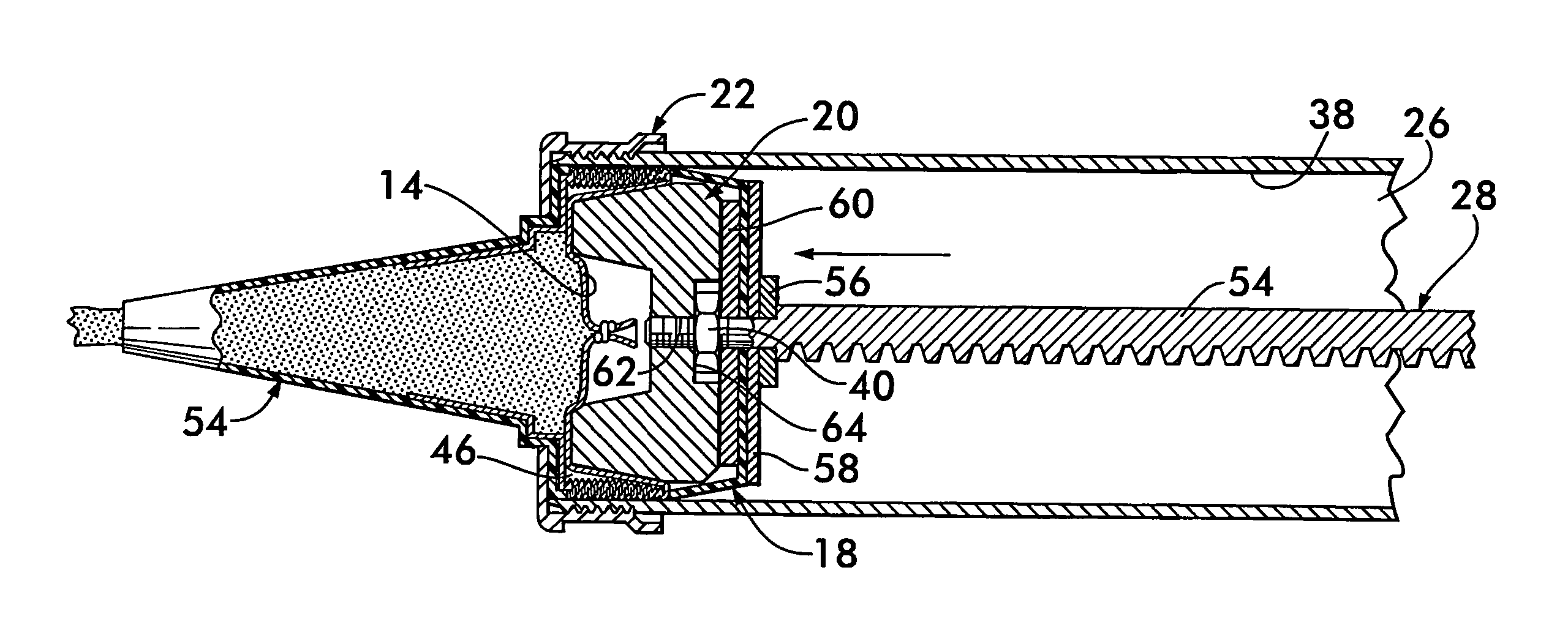
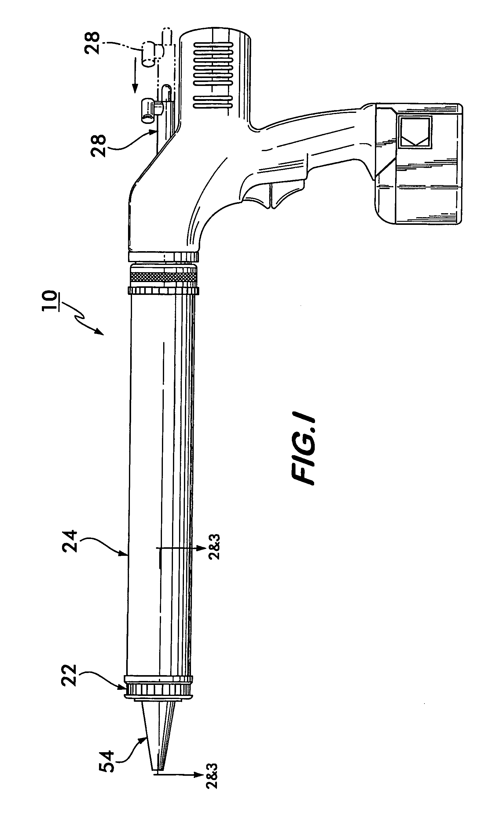
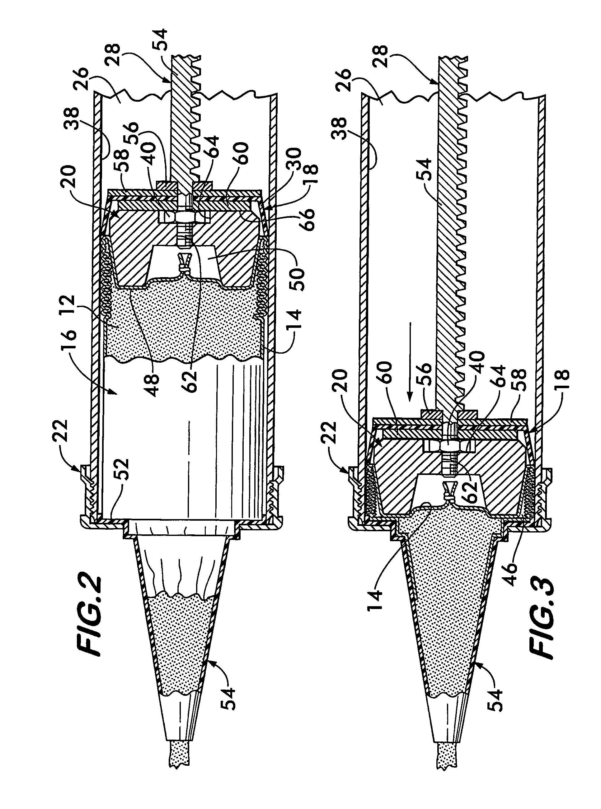
[0025]An automatically operated dispenser 10 for viscous material 12 packaged in a collapsible sleeve 14 of a sausage, or chub, package 16 in accordance with this invention is generally shown in FIGS. 1-3.

[0026]In particular, the present invention relates to a unique cooperation among a polymer piston 18, a movement-limiting member 20 secured to the piston and a closure 22 at the distal end of barrel 24. The barrel 24 includes an internal, elongate chamber 26 in which collapsible package 16 of viscous material 12 is positioned for subsequent dispensing, as is illustrated best in FIGS. 2 and 3.

[0027]It should be understood that the general configuration of the dispenser 10 illustrated in FIG. 1 is known in the art, and is being sold by Albion Engineering Company, the assignee of this invention, as its Series 1000 cordless, battery-operated dispenser. The features of the motor, actuating mechanism and cooperation between piston rod 28 and a driving gear driven by the motor (not shown)...


PUM


Abstract

A dispenser for viscous material packaged in a collapsible sleeve includes a chamber for receiving the packaged material and a piston rod and piston assembly for compressing the collapsible sleeve to dispense the viscous material through a dispensing orifice in a closure removably retained on the forward end of the chamber. The piston assembly includes a movement-limiting member having a distal surface that extends forward of a piston for limiting movement of the piston rod and piston by engaging the peripheral surface of the closure. The movement-limiting member also has an outer peripheral surface that is positioned inwardly of an inner surface of the chamber to provide an annular compartment for receiving portions of the collapsible sleeve therein when the viscous material in the sleeve has been dispensed.

Description

CROSS-REFERENCE TO RELATED APPLICATIONS[0001]This application claims the benefit of provisional Application No. 60 / 678,306, filed May 6, 2005, which is incorporated herein in its entirety.FIELD OF INVENTION[0002]This invention relates generally to a dispenser for viscous material and more particularly to a piston assembly for improving the functionality of such a dispenser. More specifically this invention has its greatest utility in connection with automatically operated (e.g., pneumatic, hydraulic and / or electrically operated) high power dispensers, but also is useful in connection with manually operated, high power dispensers. In one preferred construction, the dispenser is a battery-operated, cordless dispenser.BACKGROUND OF THE INVENTION[0003]Dispensing guns, and in particular, battery-operated, cordless dispensing guns for dispensing viscous materials such as adhesives, caulking compounds and other sealants included in a collapsible package (i.e., sometimes referred to as a “s...

Claims


Application Information

Patent Timeline
Patent Type & Authority Patents(United States)
IPC IPC(8): B67D1/00B67D99/00
CPCB05C17/00513B05C17/00583B05C17/00576B05C17/0103
Inventor SCHNEIDER, MARKHANNI, JOSEPH B.
Owner ALBION ENG
Why Eureka
Try Eureka