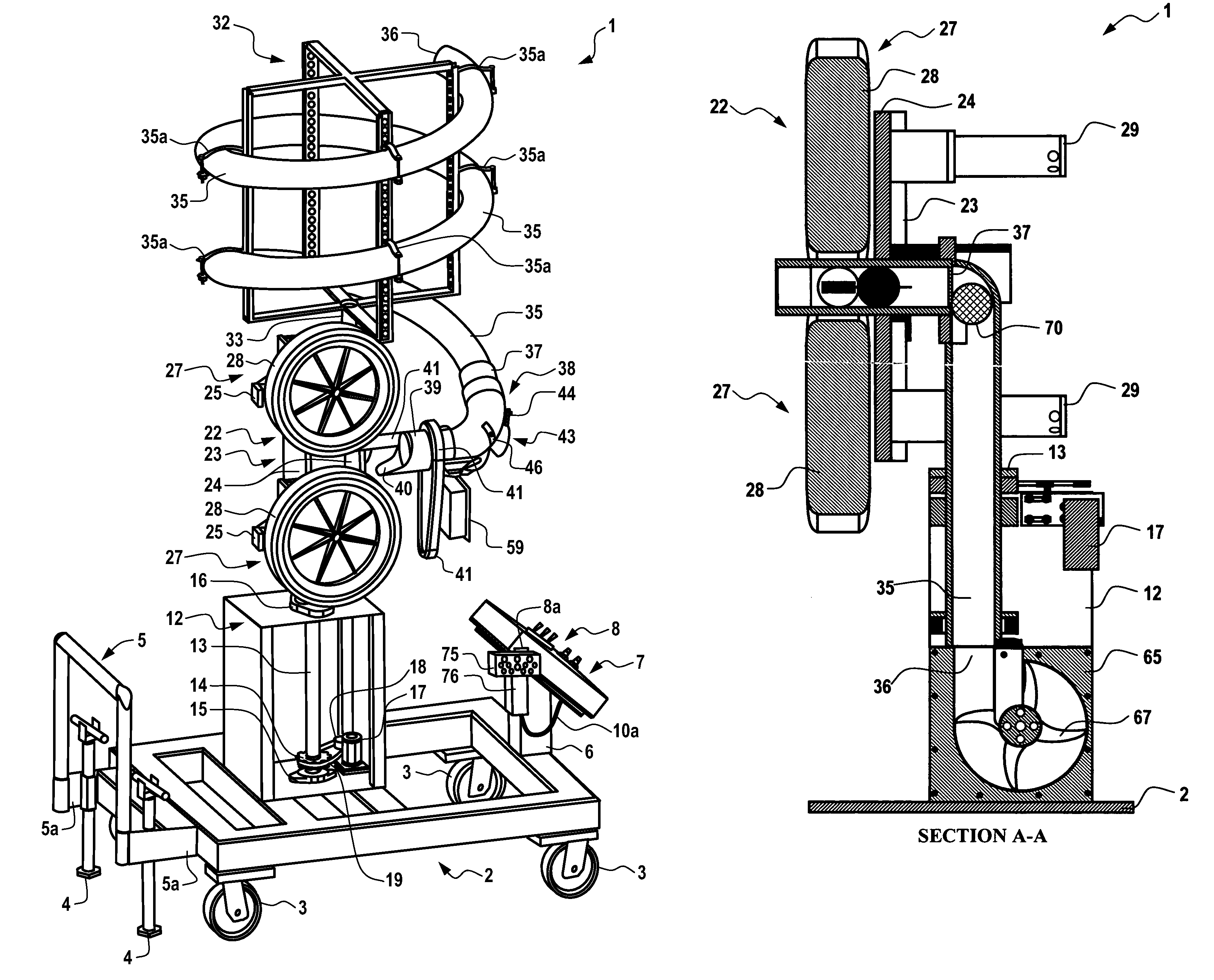
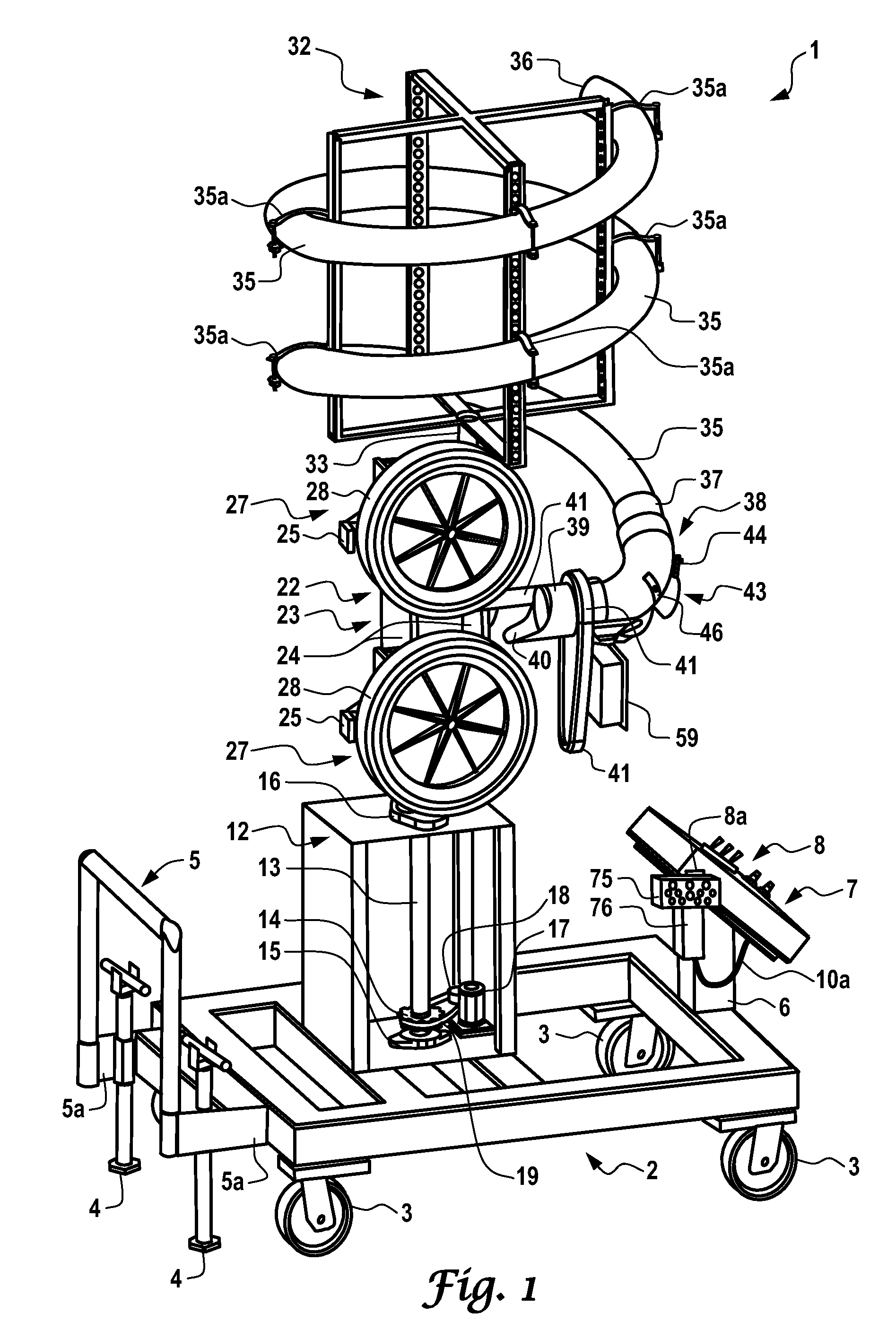
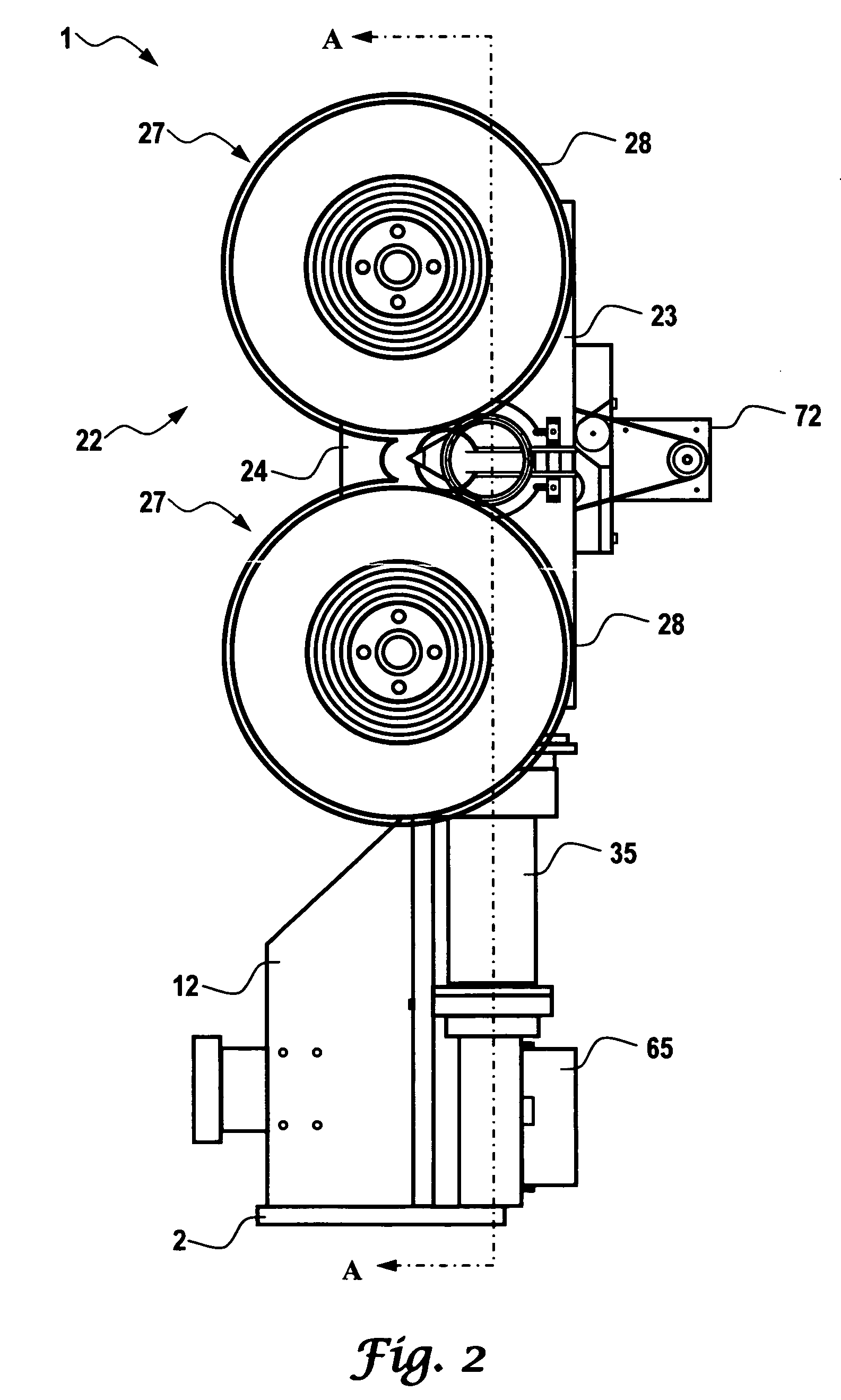
Programmable ball throwing apparatus

a technology of delivering machine and ball, which is applied in the field of programming ball throwing apparatus, can solve the problems of limited vertical and horizontal movement of conventional pitching machine, inability to purchase a machine with preprogrammed routines developed by experienced coaches, and coaches with limited experience. to facilitate the interruption of training sessions

Active Publication Date: 2010-04-06
PRECISION SPORTS ROBOTICS
View PDF30 Cites 51 Cited by
  • Summary
  • Abstract
  • Description
  • Claims
  • Application Information

AI Technical Summary

Benefits of technology

[0008]The present inventors recognized the need for an automated fungo practice aid that is able to delivery accurately an object into a three-dimensional space or landscape. The automated fungo does not rely on a person to deliver the ball to the desired position and therefore is not limited by human skill, conditioning and accuracies. The inventors realized what was needed was a bail delivery device capable of moving vertically and horizontally to allow the delivery of one or more ball to any position on a field in three-dimensions. The present invention provides a fungoman machine that is capable of consecutively delivering balls to specified positions accurately and reproducibly. The invention allows a programmable sequence, which includes variation in both field position and flight characteristics.
[0013]The present invention includes a computer program embodied on a compute readable medium for controlling the three dimensional flight and trajectory parameters of a ball including a first code segment for receiving one or more parameters identifying a flight and trajectory of a ball in three dimensions for one or more player positions and a second code segment for controlling one or more motors to eject the ball in accordance with the received one or more parameters identifying a flight and trajectory of a ball in three dimension. The computer program may be implemented to control a three dimensional ball delivery apparatus. For example, the one or more parameters identifying a flight and trajectory of a ball provide realistic ball motion characteristics such as top spin, back spin, single-hop, multi-hop, line-drive, fly ball or pop-ups.
[0015]The computer program also allows the user to define one or more of the following: the one or more parameters identifying a flight and trajectory correspond generally to the area on the field; one or more parameters identifying a flight and trajectory control a range of travel for the ball within the one or more player positions; one or more parameters identifying a flight and trajectory designating a groundball, a line drive, a fly ball or combinations thereof; one or more parameters identifying a flight and trajectory control a ball speed; and one or more parameters identifying a flight and trajectory control a ball spin. The area on the field may be the pitcher's mound, the home plate, the first base, the second base, the short stop, third base, the left field, the right field, the centerfield or combinations thereof Futhermore, the range of travel may include the extreme left side, the left side, the direct path, the right side, extreme right side or combinations thereof The present invention also allows the ball spin to be selected form the group consisting of extreme backspin, backspin, normal spin, topspin, and extreme topspin. The positions, parameters and characteristics may be displayed on a display unit graphically, symbolically, as text or as combinations thereof to allow ease of use.
[0020]The present invention also provides a method to simulate a series of plays, a partial game or an entire gone. The series of plays may include past games, hypothetical games or games based on team statistics. The method may include receiving a series of two or more of the one or more parameters identifying a flight and trajectory of a ball for one or more player positions. The members of the series correspond to the same or different player positions, thus, allowing the development of specific routines and training programs. The series may include one or more parameters specific for one or more individual position; a partial game; an entire game; one or more parameters for a specific player; one or more parameters for a specific position, one or more parameters for different types of ball flights.
[0031]Furthermore, the preset invention provides precise, repeatable placement of the launched balls. The one or more parameters identifying a flight and trajectory coed generally to an area on, the field, wherein the area is the pitcher's mound, the home plate, the first base, the second base, the short stop, the third base, the left field, the right field, the centerfield or combinations thereof. The one or more parameters may also be used to identifying a flight and trajectory and control a range of travel for the ball within the one or more player positions, wherein the range of travel includes the extreme left side, the left side, the direct path, the right side, extreme right side or combinations thereof. The present invention may provide one or more parameters identifying a flight and trajectory to designate a groundball, a line drive, a fly ball or combinations thereof.
[0032]The present invention allows a variety of combinations of parameters identifying a flight, trajectory and skill levels to provide specific skill development. Furthermore, the user interface allow control through programming, manual input, stored parameters or combinations thereof. The present invention has the capacity to facilitate interruption of a training session and repeat a ball launch for timely coaching, The wireless communication allows personal instruction of the player at the field position.

Problems solved by technology

The conventional pitching machine is limited in the degree of movement in the vertical and horizontal planes as only small degrees of movement are required to adjust pitches to the strike zone.
Furthermore, pitching machines are designed so that the vertical and horizontal movement is not readily detectable by the batter, so as not to indicate the type of pitch being thrown.
However, prior to the development of present invention, there has never been a machine specifically designed to provide experienced coaches with field practice routines geared to the development of specific player fielding skills.
Additionally, coaches with limited experience have not been able to purchase a machine with preprogrammed routines developed by a staff of experienced coaches.
The inventors realized the limited range of movement of conventional pitching machines made them ill-suited for field practice or fungo practice.

Method used


Image

  • Programmable ball throwing apparatus
  • Programmable ball throwing apparatus
  • Programmable ball throwing apparatus

Examples


Embodiment Construction

[0045]While the making and using of various embodiments of the present invention are discussed in detail below, it should be appreciated that the present invention provides many applicable inventive concepts that can be embodied in a wide variety of specific contexts. The specific embodiments discussed herein are merely illustrative of specific ways to make and use the invention and do not delimit the scope of the invention.

[0046]To facilitate the understanding of this invention, a number of terms are defined below. Terms defined herein have meanings as commonly understood by a person of ordinary skill in the areas relevant to the present invention. Terms such as “a”, “an” and “the” are not intended to refer to only a singular entity, but include the general class of which a specific example may be used for illustration The terminology herein is used to describe specific embodiments of the invention, but their usage does not delimit the invention, except as outlined in the claims.

[0...


PUM


Abstract

The present invention includes programs, devices and methods for a programmable ball throwing machine that is able to eject balls to preset, programmed or manually-selected positions with programmable projection and travel characteristics. The present invention includes a computer implemented method for controlling the parameters of a ball flight and trajectory in three dimensions including one or more parameters to identify a flight and trajectory of a ball in three dimensions for one or more player positions and a processor to control one or more motors in response to the one or more parameters.

Description

CROSS-REFERENCE TO RELATED APPLICATIONS[0001]This application claims priority to U.S. Provisional Patent Application, Ser. No. 60 / 516,396; entitled “Programmable Ball Throwing Apparatus” filed Nov. 3, 2003.TECHNICAL FIELD OF THE INVENTION[0002]The present invention relates in general to the field of ball delivery devices and, more particularly, to programs, devices and methods for programming a ball delivering machine that is able to deliver balls to preset, programmed or manually selected positions with programmable travel characteristics.BACKGROUND OF THE INVENTION[0003]Without limiting the scope of the invention, its background is described in connection with devices, programs and methods relating to baseball, as an example.[0004]Heretofore, in this field, a common training aid is the baseball pitching machine. Primarily, pitching machines are used for batting practice to simulate a human pitcher. Conventional pitching machines arm used to pitch a variety of different pitches inc...

Claims


Application Information

Patent Timeline
Patent Type & Authority Patents(United States)
IPC IPC(8): A63B69/40A63B65/12A63BA63B47/00A63B69/00A63B69/38F41F7/00
CPCA63B69/406A63B47/002A63B69/38A63B2069/0008A63B2069/0011A63B2069/402A63B2243/0095A63B2243/0025A63B2243/0041A63B2243/0045A63B2243/005A63B2243/0079A63B2243/0008A63B2102/24A63B2102/14A63B2102/065A63B2102/22A63B2102/182
Inventor CUCJEN, ROMULO J.DURON, DENNIS RANDALL
Owner PRECISION SPORTS ROBOTICS
Why Eureka
Try Eureka