
Method and apparatus for reconstruction of 3D image volumes from projection images

a technology of projection images and volume reconstruction, applied in image data processing, diagnostics, applications, etc., can solve the problems of high computation and high cost of reconstruction images of volume volumes from two-dimensional measured projection images, and achieve the effect of less cost and efficient reconstruction imaging

Active Publication Date: 2010-04-06
PME IP
View PDF127 Cites 88 Cited by
  • Summary
  • Abstract
  • Description
  • Claims
  • Application Information

AI Technical Summary

Benefits of technology

The invention provides improvements in reconstructing the density distribution of a volume using measured projection images. It uses a graphics processing unit (GPU) to reconstruct the volume by initializing to arbitrary values the density distribution and then iteratively determining the actual density distribution of each voxel in the volume. The GPU can use slices of the volume to map the density distribution to the voxels in the slices. The invention can be used in computed tomography, magnetic resonance imaging, and other fields.

Problems solved by technology

Reconstructive imaging—that is, the construction of a three-dimensional representation (image) of a volume from two-dimensional measured projection images of that volume, e.g., obtained by an x-ray imaging apparatus—is highly computation intensive.
Though prior art solutions have proven effective in this regard, they are typically quite expensive.
Moreover, many prior solutions—particularly, for example, those, for determining back-projections have limited applicability to a new class of imaging, referred to as tomosynthesis, in which a relatively small number of projection images are required from only a limited number of x-ray source positions (or foci).

Method used


Image

  • Method and apparatus for reconstruction of 3D image volumes from projection images
  • Method and apparatus for reconstruction of 3D image volumes from projection images
  • Method and apparatus for reconstruction of 3D image volumes from projection images

Examples


Embodiment Construction

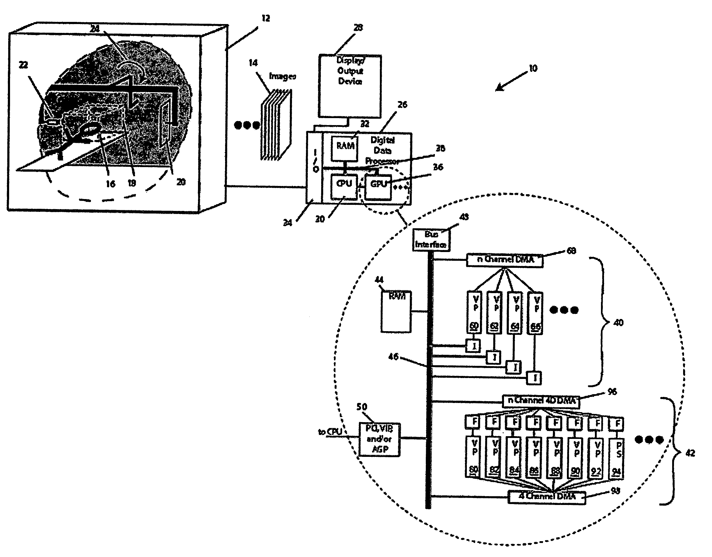
[0029]Described below are methods and apparatus for reconstruction of three-dimensional volumetric representations, e.g., from a plurality of two-dimensional measured projection images. The illustrated embodiments employ the capabilities of chips and chip sets, boards and / or processor configurations known as “graphics processing units” (GPUs) to more efficiently process measured projection images of a volume to reconstruct a density distribution associated with that volume, though the methods and apparatus described herein may be implemented on general purpose processors, special purpose processors. Still other embodiments use no GPU at all, relying on the CPU and / or other co-processing functionality (such as floating point units, array processors, and so forth) to provide or supplement such processing, all in accord with the teachings hereof.

[0030]The invention has application, for example, in medical imaging such as computed tomography (CT), position emission tomogpraphy (PET), si...


PUM

PropertyMeasurementUnit
computed tomographyaaaaaaaaaa
density distributionaaaaaaaaaa
volumeaaaaaaaaaa

Abstract

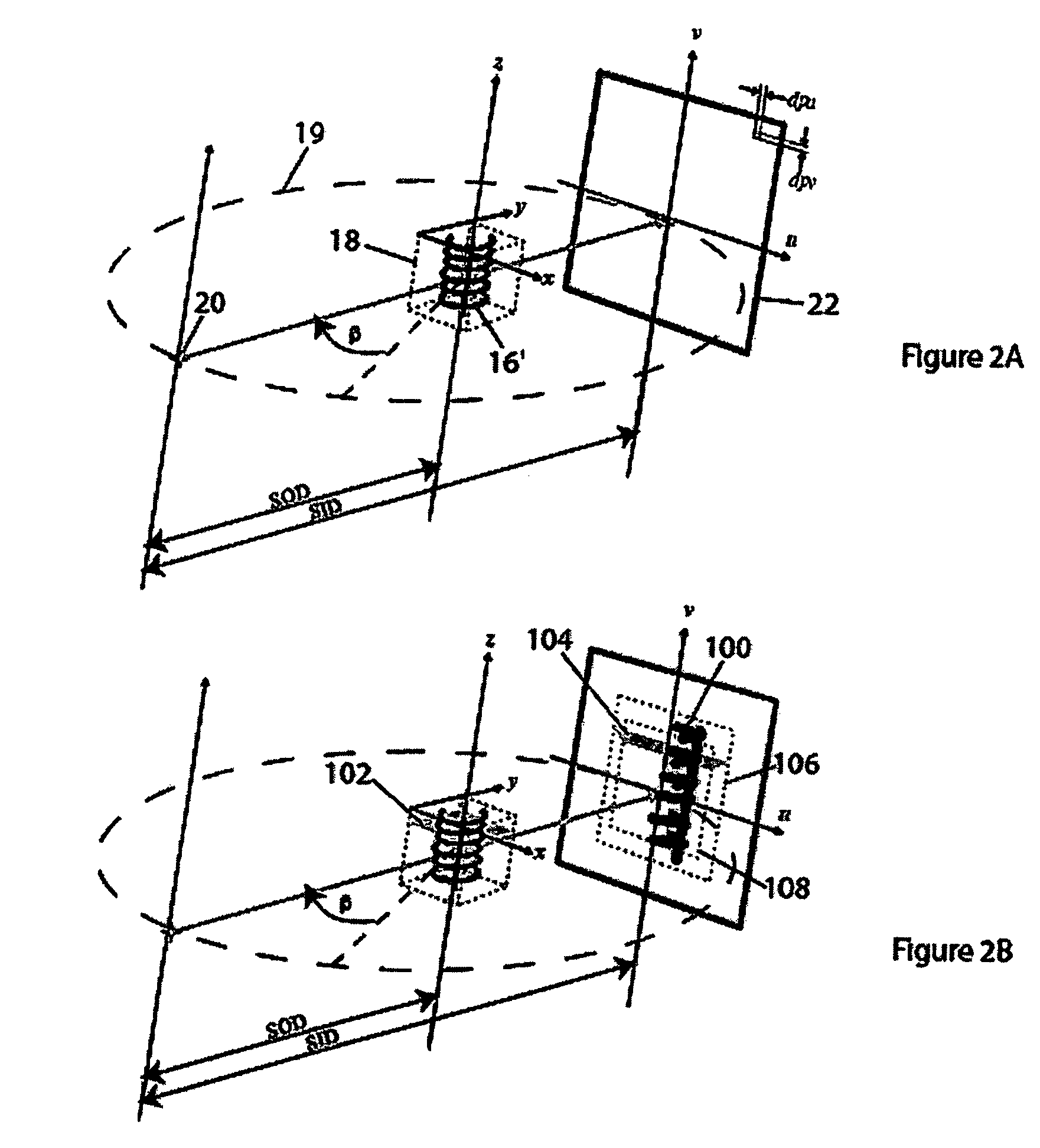
The invention provides improvements in reconstructive imaging of the type in which a volume is reconstructed from a series of measured projection images (or other two-dimensional representations) by utilizing the capabilities of graphics processing units (GPUs). In one aspect, the invention configures a GPU to reconstruct a volume by initializing an estimated density distribution of that volume to arbitrary values in a three-dimensional voxel-based matrix and, then, determining the actual density distribution iteratively by, for each of the measured projections, (a) forward-projecting the estimated volume computationally and comparing the forward-projection with the measured projection, (b) generating a correction term for each pixel in the forward-projection based on that comparison, and (c) back-projecting the correction term for each pixel in the forward-projection onto all voxels of the volume that were mapped into that pixel in the forward-projection.

Description

RELATED APPLICATIONS[0001]The present invention claims priority to a U.S. provisional application entitled “Method and Apparatus for Reconstruction of 3D-Image Volumes from Projection Images,” filed Oct. 29, 2004 having a Ser. No. 60 / 623,410, the teachings of which are incorporated herein by reference.[0002]The present invention also claims priority, as a continuation-in-part (CIP) application, to a U.S. patent application entitled “Improved Methods and Apparatus for Back-Projection and Forward-Projection,” filed Jan. 12, 2004 now U.S. Pat. No. 7,120,283 and having a Ser. No. 10 / 756,172, which is herein incorporated by reference.BACKGROUND OF THE INVENTION[0003]The invention relates generally to digital data processing and, particularly, to reconstructive imaging. The invention has application in heath care and, specifically, medical imaging—as well as in a host of other areas, such as industry, research and defense.[0004]Reconstructive imaging—that is, the construction of a three-d...

Claims


Application Information

Patent Timeline
Patent Type & Authority Patents(United States)
IPC IPC(8): G06K9/00G01N23/00
CPCG06T11/006G06T2211/428Y10S128/922
Inventor STALLING, DETLEVWESTERHOFF, MALTESEEBASS, MARTINKUBIS, RALF
Owner PME IP
Learn More