Direct contact thermal exchange heat engine or heat pump

a heat exchange heat engine and direct contact technology, applied in the field of thermodynamic engines, can solve the problems of many thermodynamic cycles that convert thermal energy into work or vice versa, and inherently limit the efficiency of less than 100%

Inactive Publication Date: 2010-04-13
COOL ENERGY
View PDF61 Cites 41 Cited by
  • Summary
  • Abstract
  • Description
  • Claims
  • Application Information

AI Technical Summary

Problems solved by technology

Many thermodynamic cycles that transform thermal energy into work or vice versa are inherently limited to an efficiency that is less than 100% of the fundamental Carnot efficiency limit.

Method used


Image

  • Direct contact thermal exchange heat engine or heat pump
  • Direct contact thermal exchange heat engine or heat pump
  • Direct contact thermal exchange heat engine or heat pump

Examples


Embodiment Construction

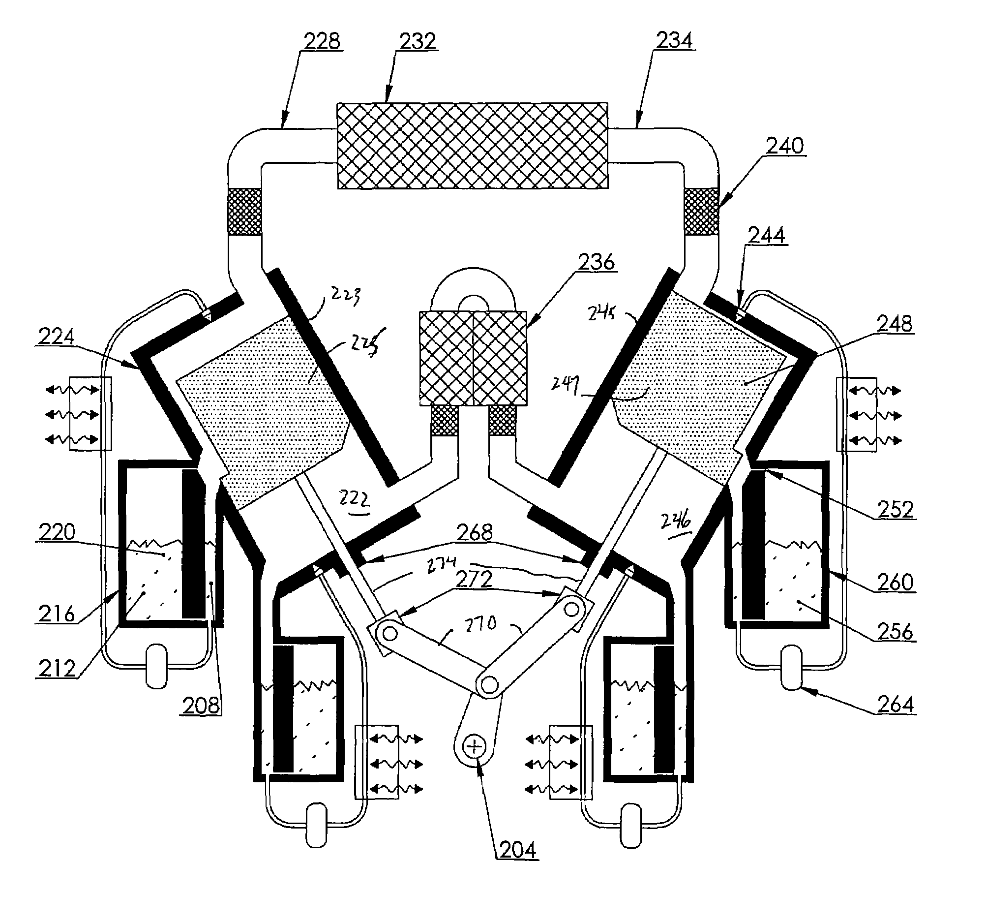
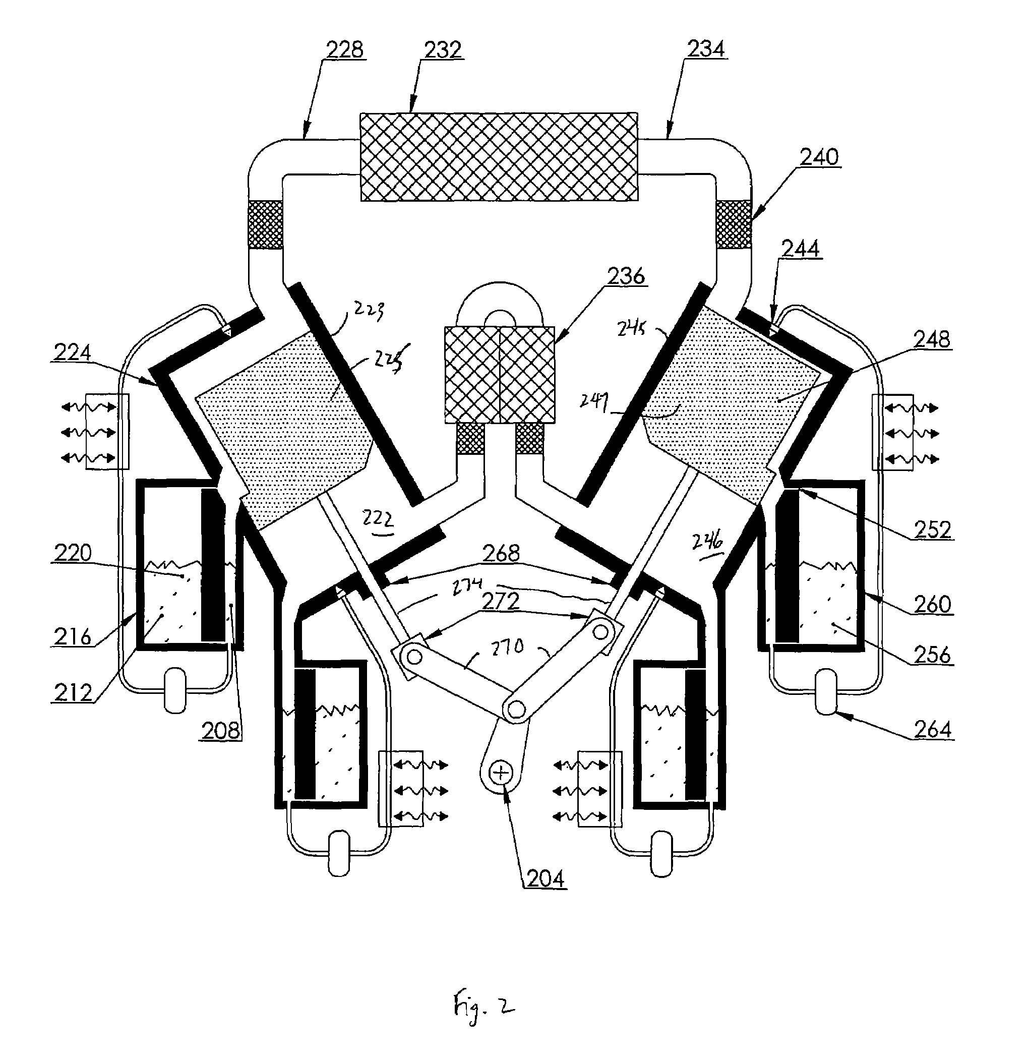
[0012]The term “thermodynamic engines” as used throughout this disclosure generally includes “heat engines” and “heat pumps”; when describing physical processes of the invention, the pertinent operations of heat engines may be inverted when necessary to describe the operation of heat pumps.

[0013]The inventors have recognized that deficiencies in improving the efficiency of thermodynamic engines may be linked to the fact that in practice, heat addition and heat rejection processes in such engines are not strictly isothermal. The limits to achieving 100% Carnot efficiency with a thermodynamic cycle that has strictly isothermal heat addition and heat rejection processes, however, would be entirely practical and not thermodynamic. Embodiments of the invention therefore realize better isothermal heat addition and heat rejection processes within a heat engine or a heat pump.

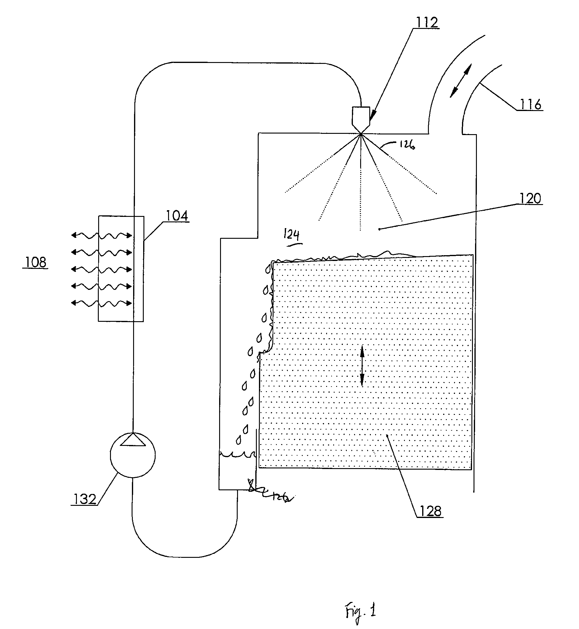
[0014]A basic principle used in embodiments of the invention is illustrated with FIG. 1, which provides a schematic ...


PUM


Abstract

Systems and methods for operating a thermodynamic engine are disclosed. The systems and methods may effect cyclic motion of a working fluid between hot and cold regions of a thermodynamic engine and inject a dispersible material into the working fluid at the hot or cold region during a heat-addition or heat-rejection process. The system and methods may also evacuate the dispersible material from the hot or cold region.

Description

CROSS REFERENCE TO RELATED APPLICATION[0001]This application is a nonprovisional of, and claims the benefit of the filing date of, U.S. Prov. Pat. Appl. No. 60 / 954,641, entitled “DIRECT CONTACT THERMAL EXCHANGE HEAT ENGINE OR HEAT PUMP,” filed Aug. 8, 2007 by Lee S. Smith and Samuel P. Weaver, the entire disclosure of which is incorporated herein by reference for all purposes.BACKGROUND OF THE INVENTION[0002]This application relates generally to thermodynamic engines, including heat pumps. More specifically, this application relates to a direct-contact thermal-exchange heat engine or heat pump.[0003]Many thermodynamic cycles that transform thermal energy into work or vice versa are inherently limited to an efficiency that is less than 100% of the fundamental Carnot efficiency limit. This shortcoming arises because the addition or rejection of heat may take place at points in the thermodynamic cycle other than at the hottest and coldest temperature limits. There therefore exists a ne...

Claims


Application Information

Patent Timeline
Patent Type & Authority Patents(United States)
IPC IPC(8): F01B29/10F25B9/00F02G1/04
CPCF25B9/00
Inventor SMITH, LEE S.WEAVER, SAMUEL P.NUEL, BRIAN P.VERMEER, WILLIAM H.
Owner COOL ENERGY
Why Eureka
Try Eureka