Optical subassembly having insertable cylindrical sleeve

a cylindrical sleeve and sub-assembly technology, applied in the field of optical sub-assembly, can solve the problems of reducing the production of shavings during connector insertion or removal, and achieve the effects of low cost, improved wiggle performance, and formed and machined

Active Publication Date: 2010-04-13
II VI DELAWARE INC
View PDF4 Cites 116 Cited by
  • Summary
  • Abstract
  • Description
  • Claims
  • Application Information

AI Technical Summary

Benefits of technology

[0014]The OSA body is composed of a relatively soft material, which enables it to be formed and machined at a low cost. In contrast, the sleeve is composed of a relatively hard material, such as zirconium or glass ceramic, which matches the hardness of the optical fiber connector material. Thus, the sleeve resists deformation or metal migration, two prevalent causes of the hard plug problems described above. Also, because of its hardness and the fact that it is not a split sleeve, the OSA sleeve improves wiggle performance by restricting movement of the connector when wiggled while received in the sleeve. Further, zirconium or other acceptable hard materials desirably reduce the production of shavings during connector insertion or removal.
[0015]In particular, the sleeve serves as the contact surface when the optical fiber connector is received in the plug receptacle. As such, it protects the softer material of the rest of the plug receptacle by absorbing the frictional forces associated with connector insertion and removal. Thus, forming the OSA body and plug receptacle out a cheaper, softer material does not impact the quality or function of the OSA.

Problems solved by technology

Thus, the sleeve resists deformation or metal migration, two prevalent causes of the hard plug problems described above.
Further, zirconium or other acceptable hard materials desirably reduce the production of shavings during connector insertion or removal.

Method used


Image

  • Optical subassembly having insertable cylindrical sleeve
  • Optical subassembly having insertable cylindrical sleeve
  • Optical subassembly having insertable cylindrical sleeve

Examples


Embodiment Construction

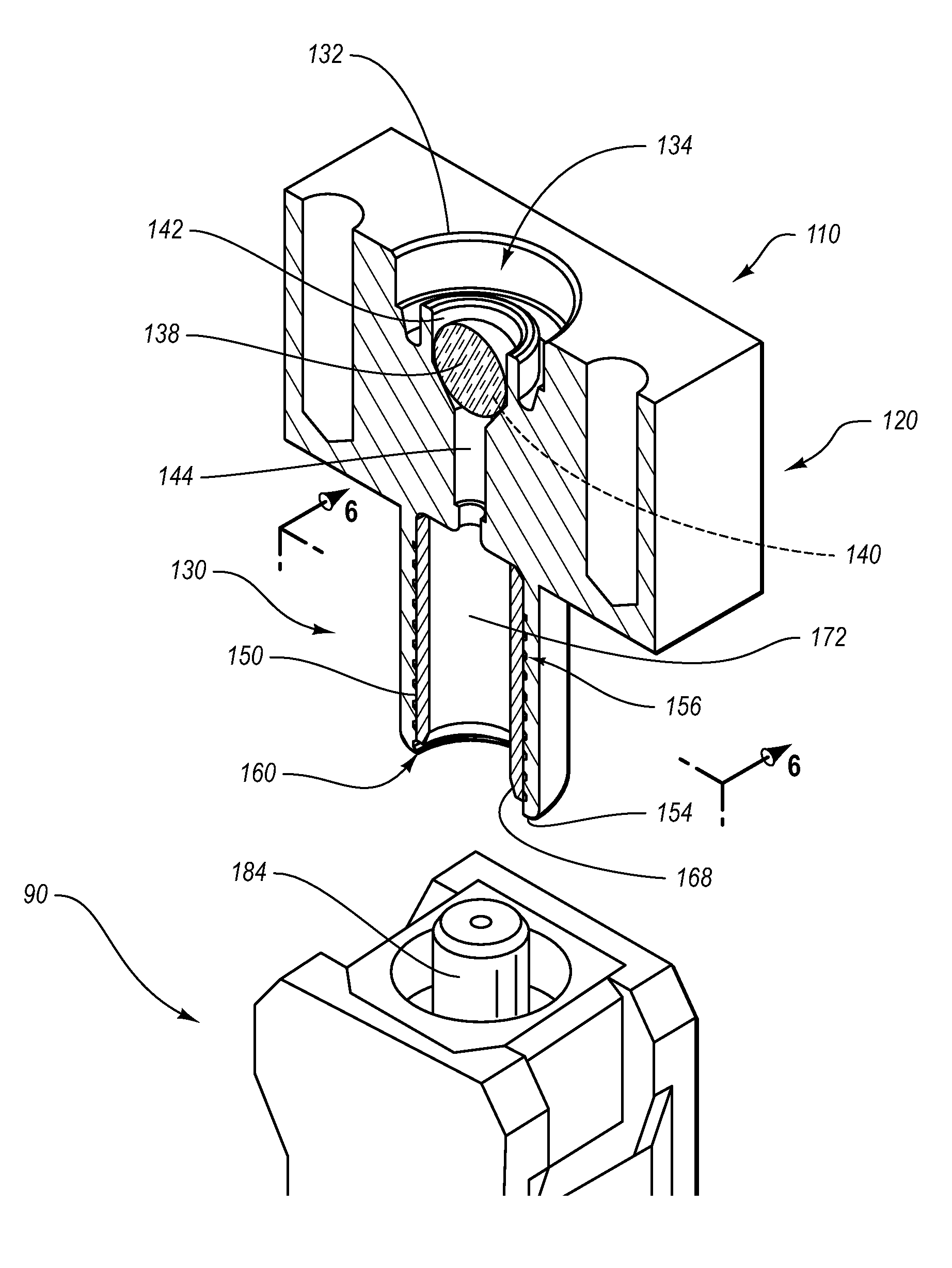
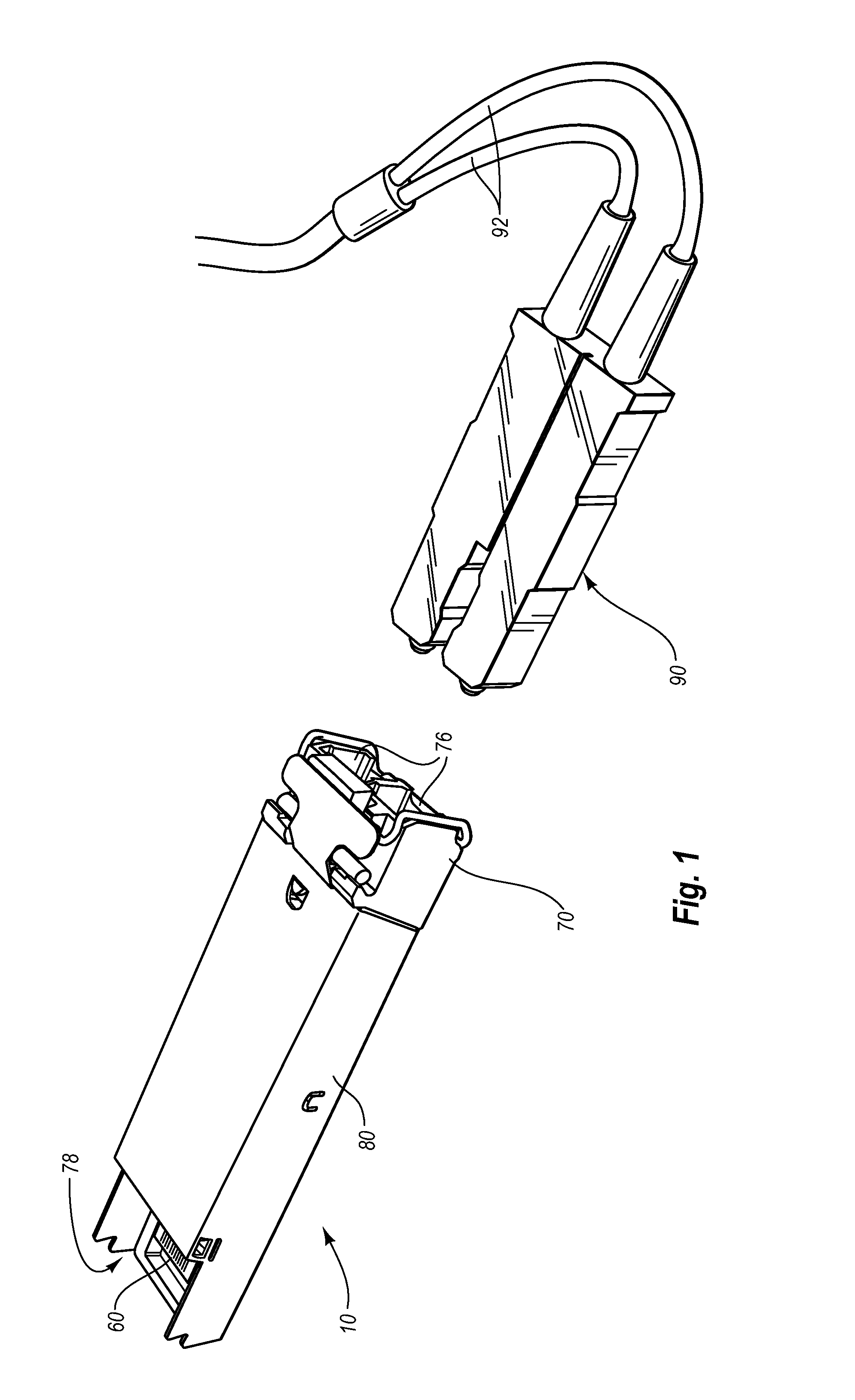
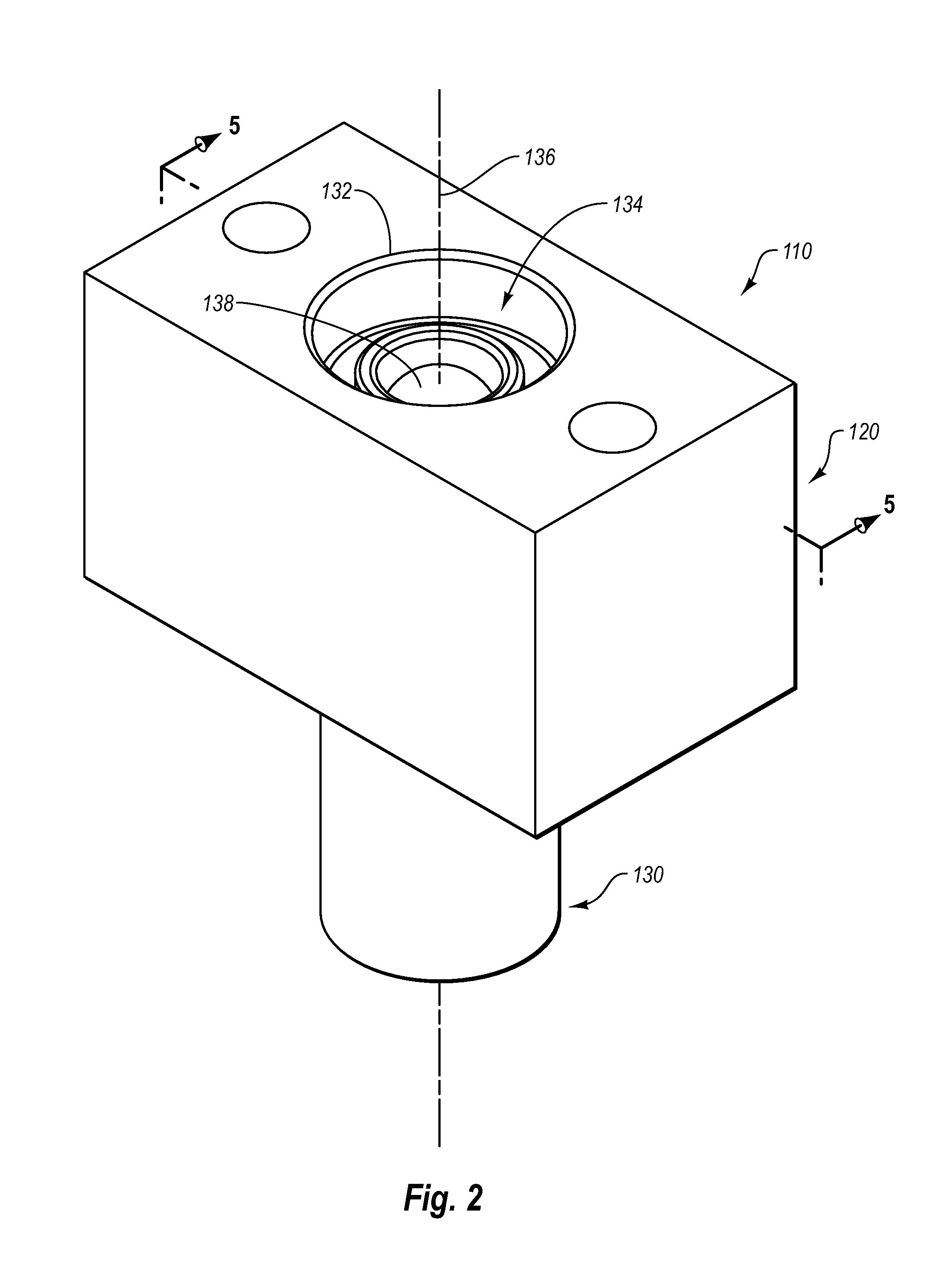
[0026]Reference will now be made to figures wherein like structures will be provided with like reference designations. It is understood that the drawings are diagrammatic and schematic representations of exemplary embodiments of the invention, and are not limiting of the present invention nor are they necessarily drawn to scale.

[0027]FIGS. 1-7 depict various features of embodiments of the present invention, which are generally directed to an optical subassembly for use in optical transmitters and receivers, such as those found in an optical transceiver module. The optical subassembly includes a port configured for receiving a connector of an optical fiber. The port includes a receptacle defined by the optical subassembly housing, and a hollow cylindrical sleeve that is press fit in the receptacle. This port configuration substantially eliminates challenges previously encountered in the art, including hard plug, wiggle performance, and shaving production. Further, the present optical...


PUM


Abstract

An optical subassembly (“OSA”) for use in optical communications modules is disclosed. The OSA solves various issues related to the insertion and removal of an optical fiber connector into and from the OSA receptacle, including hard plug, wiggle performance, and shavings production. In one embodiment, an optical communications module is disclosed and includes a housing and an optical subassembly of the present invention partially contained within the housing. The optical subassembly includes various components, including a body composed of a first material, and a plug receptacle formed with the body. The plug receptacle includes an inner surface on which surface features, such as threads, are formed. A hollow cylindrical sleeve composed of a second material is received in the plug receptacle such that the outer sleeve surface engages the surface features of the plug receptacle inner surface and such that an optical fiber connector can be received by the sleeve.

Description

BACKGROUND[0001]1. Technology Field[0002]The present invention generally relates to optical transmitters and receivers. In particular, the present invention relates to an optical subassembly that is configured to eliminate problems relating to hard plugging, fiber wiggle, and shavings when connecting with an optical fiber.[0003]2. The Related Technology[0004]Optical transceivers are used to transmit and receive optical signals from an optical network and to enable electrical network components to interface with and communicate over optical networks. Many optical transceivers are modular and are designed in accordance with industry standards that define mechanical aspects of the transceivers, form factors, optical and electrical requirements, and other characteristics and requirements of the transceivers. For example the Small Form-Factor Module Multi-Source Agreement (“SFF MSA”), the Small Form-Factor Pluggable Module Multi-Source Agreement (“SFP MSA”) and the 10 Gigabit Small Form ...

Claims


Application Information

Patent Timeline
Patent Type & Authority Patents(United States)
IPC IPC(8): G02B6/36G02B6/38
CPCG02B6/4292G02B6/4204G02B6/4246
Inventor TEO, TAT MINGTOGAMI, CHRIS KIYOSHILIU, JINXIANG
Owner II VI DELAWARE INC
Why Eureka
Try Eureka