
Advanced image intensifier assembly

a technology of image intensifier and assembly, which is applied in the field of advanced image intensifier, can solve the problems of device inoperativeness and useless device, and achieve the effect of improving work ability and enhancing functionality

Inactive Publication Date: 2010-04-13
SALDANA MICHAEL R
View PDF38 Cites 7 Cited by
  • Summary
  • Abstract
  • Description
  • Claims
  • Application Information

AI Technical Summary

Benefits of technology

[0013]In one aspect, an advanced image intensifier assembly provides enhanced functionality. A grounded photocathode provides shielding from electromagnetic interference, improving the ability to work in multiple light conditions. Bi-directional wireless communication and non-volatile storage allow critical information to be permanently stored and read wirelessly at a scanning station, easing identification of units. Because bi-directional communication components can be embedded within an image intensifier assembly, existing end-user night vision devices can be upgraded by simply replacing the image intensifier assembly. For enhanced safety, a programmable shutdown capability is provided. This renders the device inoperative in the absence of continuous input, either wireless or manual, from an authorized operator, thus rendering the device useless if captured by enemy combatants. Finally, direct 1-volt operation enables the device to be powered by, for example, a single AA battery.

Problems solved by technology

This renders the device inoperative in the absence of continuous input, either wireless or manual, from an authorized operator, thus rendering the device useless if captured by enemy combatants.

Method used


Image

  • Advanced image intensifier assembly
  • Advanced image intensifier assembly
  • Advanced image intensifier assembly

Examples


Embodiment Construction

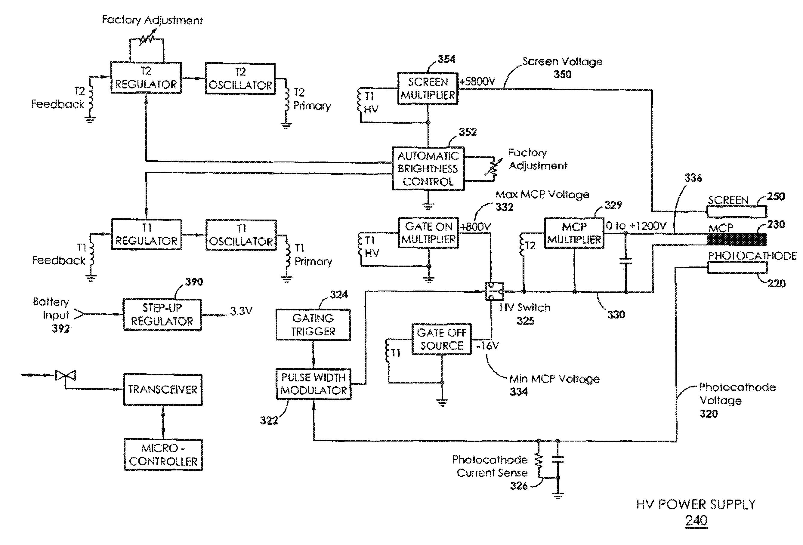
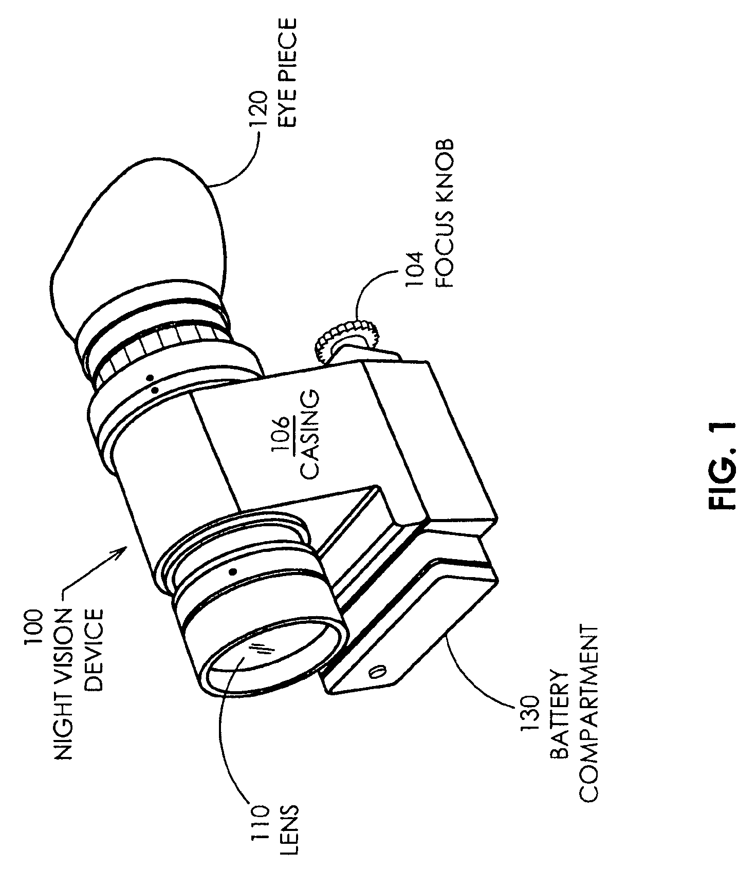
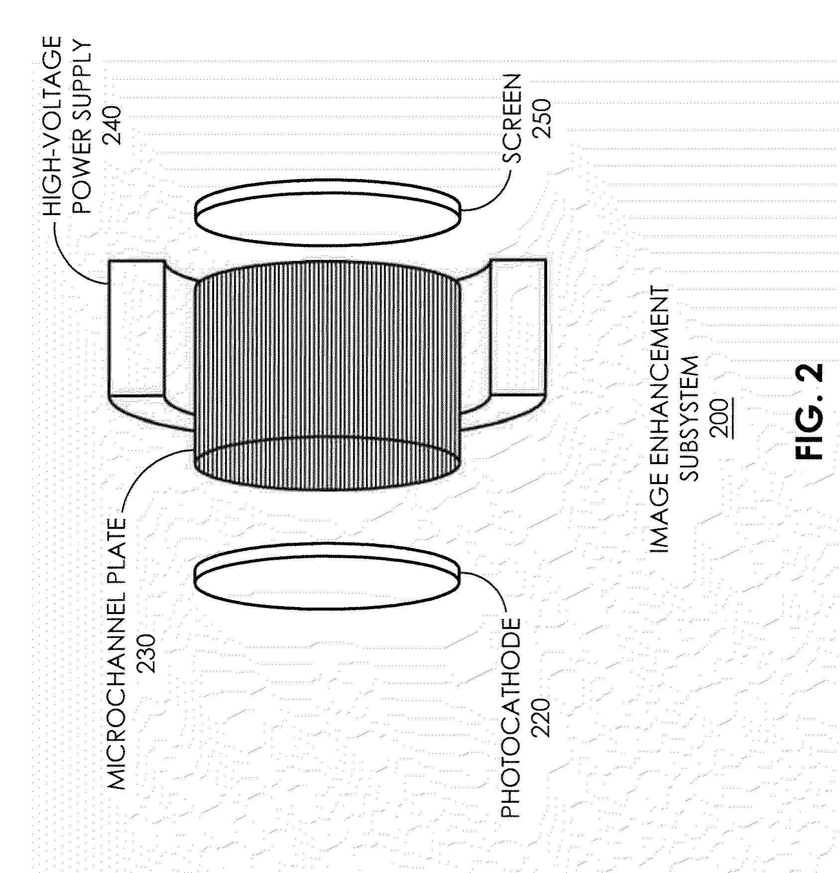
[0014]A night vision device according to the present specification may include an image intensifier module self-contained in a tube and comprising a photocathode, a microchannel plate, and a screen, which may be a phosphorescent screen. The image intensifier is powered by a high-voltage power supply, which in some embodiments is in a wrap-around configuration, and which may be encased in epoxy or other protective material. The power supply may provide at least one gated voltage. In the prior art, it is common to provide a gated voltage to the photocathode. In at least some cases, this proved problematic for image intensifiers intended for use in various light conditions. In particular, daylight operation requires a short duty cycle. But short rise and fall times resulted in excessive EMI. In contrast, the present specification discloses an arrangement whereby the MCP voltage is gated instead of the photocathode voltage. The photocathode is fixed at or near a reference voltage, which...


PUM


Abstract

An advanced image intensifier assembly provides enhanced functionality. A grounded photocathode provides shielding from electromagnetic interference, improving the ability to work in multiple light conditions. Bi-directional wireless communication and non-volatile storage allow critical information to be permanently stored and read wirelessly at a scanning station, easing in identification of units. Because bi-directional communication components can be embedded within an image intensifier assembly, existing end-user night vision devices can be upgraded by simply replacing the image intensifier assembly. For enhanced safety, a programmable shutdown capability is provided. This renders the device inoperative in the absence of continuous input, either wireless or manual, from an authorized operator, thus rendering the device useless if captured by enemy combatants. Finally, direct 1-volt operation enables the device to be powered by, for example, a single AA battery.

Description

CROSS REFERENCE TO RELATED APPLICATIONS[0001]This application claims priority to U.S. provisional application 61 / 001,022 filed Oct. 30, 2007 entitled “Advanced Image Intensifier Assembly,” which is hereby incorporated by reference. U.S. patent application Ser. No. 12 / 205,751, entitled “Image Intensifier with Adjustable Figure of Merit,” is also hereby incorporated by reference.BACKGROUND[0002]This specification relates to the field of night vision devices, and more particularly to an advanced image intensifier.[0003]Image intensifiers are used in night vision devices to enhance images in low light conditions. As a general principle of operation, photons representing an image are converted into electrons, which are then substantially amplified, and finally the enhanced electron stream is again converted to photons on a phosphorescent screen, yielding a green image. There are at least four recognized “generations” of night vision technology, with the generations characterized by incre...

Claims


Application Information

Patent Timeline
Patent Type & Authority Patents(United States)
IPC IPC(8): H01J40/14H01J43/00
CPCG02B23/12H01J43/08H01J31/507H01J2231/5016
Inventor SALDANA, MICHAEL R.
Owner SALDANA MICHAEL R
Learn More