
Reading codes of RFID tags incoming at premises and removing them later as they exit

Active Publication Date: 2010-04-13
IMPINJ
View PDF2 Cites 25 Cited by
  • Summary
  • Abstract
  • Description
  • Claims
  • Application Information

AI Technical Summary

Benefits of technology

[0015]In warehouse-type embodiments, the actionable codes can be used to activate an Electronic Article Surveillance (EAS) system, to prevent theft. This can reduce operational costs, which can result in savings to be passed on to the consumers in the form of lower prices.
[0017]An advantage of some embodiments is that a personal tag will not trigger an RFID system of the premises when it should not. Thus, due to the personal tag, a sale that should not be registered at a POS station will not be so registered. Moreover, an alarm that should not be activated at an EAS station will not be so activated.
[0018]In some embodiments, the personal codes are further discarded without ever looking up what they mean. This way, consumer privacy is better protected.

Problems solved by technology

A problem arises upon recognizing that RFID readers installed at premises will be able to also read, in addition to tags of the items, tags that are foreign to the RFID environment of the premises.

Method used


Image

  • Reading codes of RFID tags incoming at premises and removing them later as they exit
  • Reading codes of RFID tags incoming at premises and removing them later as they exit
  • Reading codes of RFID tags incoming at premises and removing them later as they exit

Examples


Embodiment Construction

proceeds with reference to the accompanying Drawings, in which:

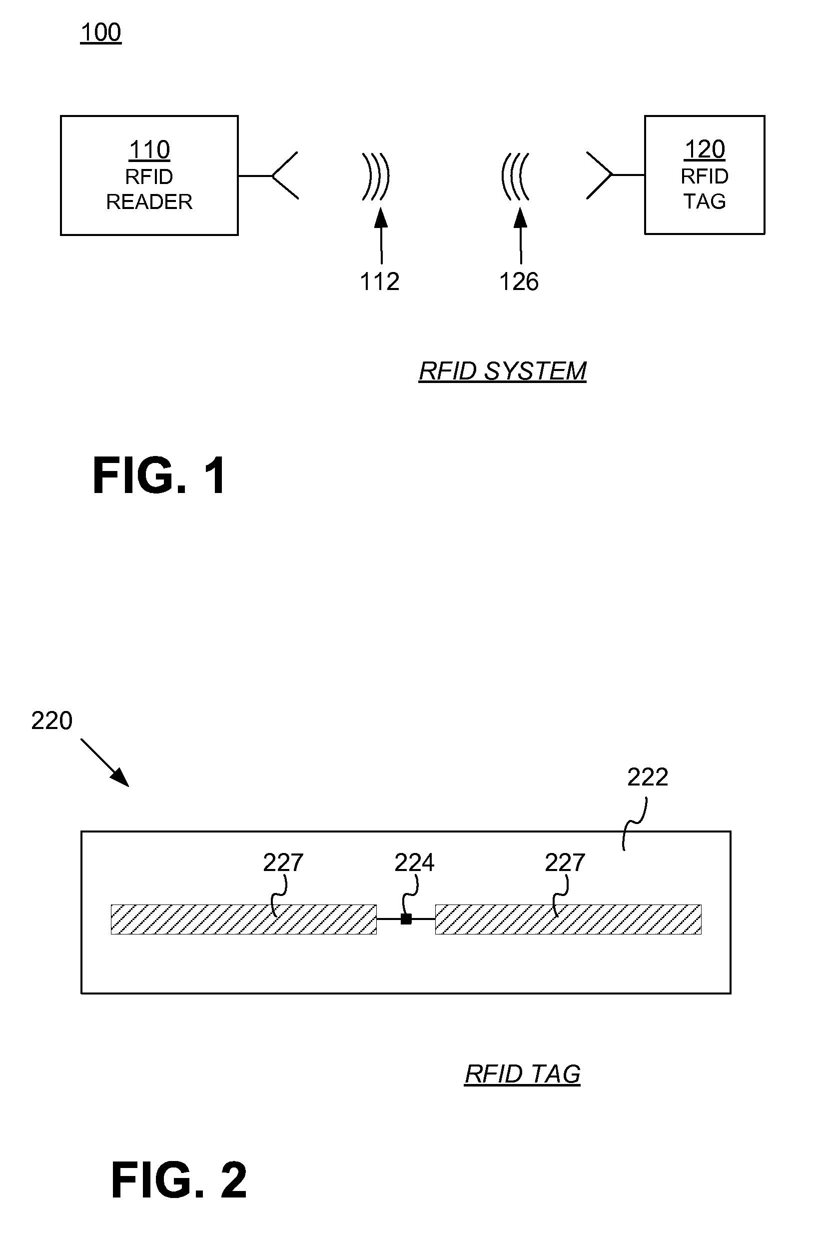
[0021]FIG. 1 is a block diagram of components of an RFID system.

[0022]FIG. 2 is a diagram showing components of a passive RFID tag, such as a tag that can be used in the system of FIG. 1.

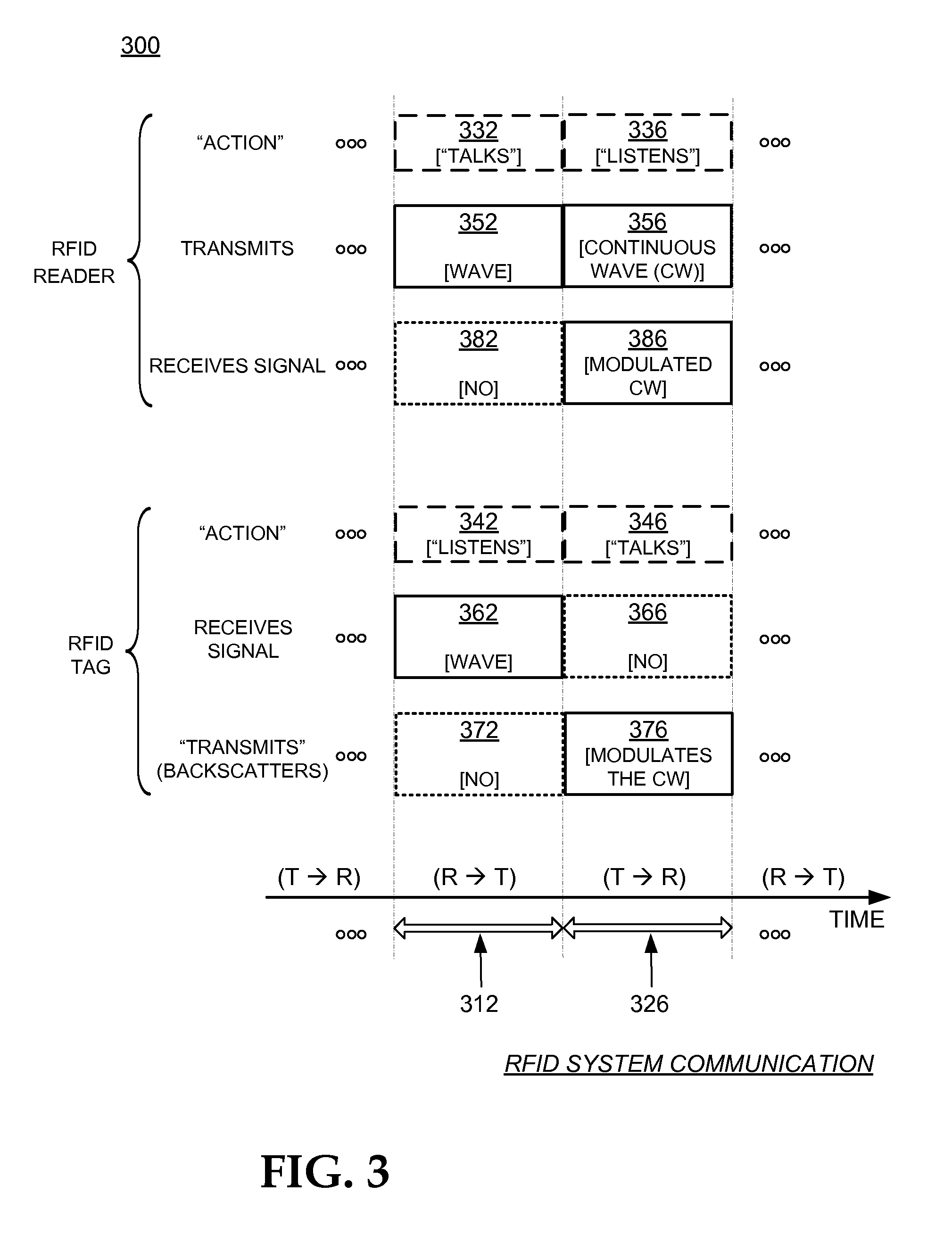
[0023]FIG. 3 is a conceptual diagram for explaining a half-duplex mode of communication between the components of the RFID system of FIG. 1.

[0024]FIG. 4 is a block diagram showing a detail of an RFID reader system, such as the one shown in FIG. 1.

[0025]FIG. 5 is a block diagram of a whole RFID reader system according to embodiments.

[0026]FIG. 6 is a diagram showing a prior art implementation for a Point-Of-Sale (POS) arrangement.

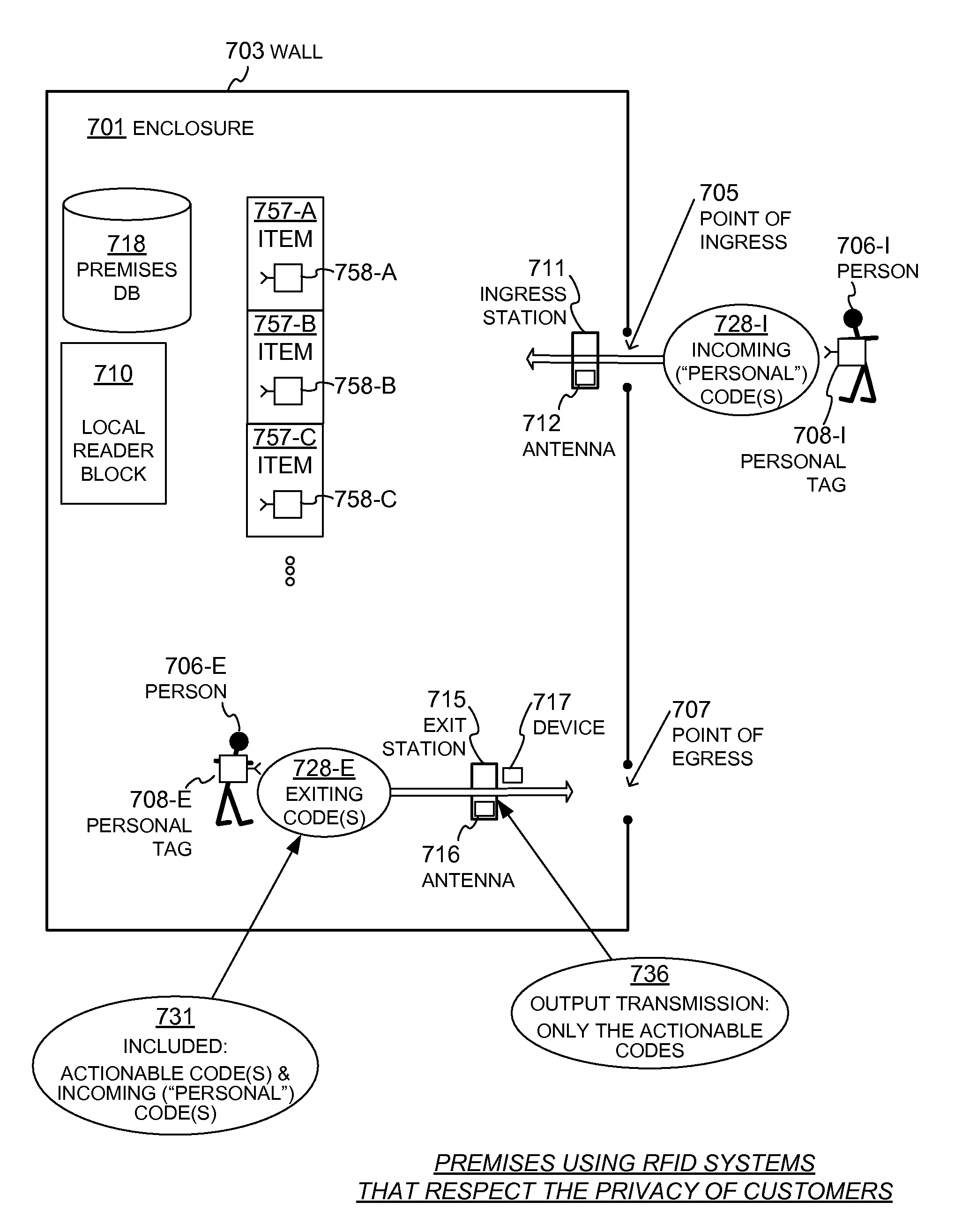
[0027]FIG. 7 is a plan view of premises with an RFID system that respects privacy of its customers, according to embodiments.

[0028]FIG. 8 is a plan view of premises according to embodiments, in which an exit station is implemented by a Point-Of-Sale (POS) station.

[0029]FIG. 9 is a plan view of premises according ...


PUM


Abstract

RFID reader systems, components, software and methods are provided for use premises that have RFID-tagged items. When a person comes onto an enclosure of the premises already carrying a personal tag, the incoming code of that personal tag is read. When later the person exits the enclosure, they could be transporting some of the items that have actionable codes. The actionable codes can be read, but the incoming code can be removed from them, before the actionable codes are acted upon, in Point-of-Sale or Electronic Article Surveillance systems.

Description

RELATED APPLICATIONS[0001]This application claims priority from U.S.A. Provisional Application Ser. No. 60 / 902,748 filed on 2007 Feb. 21, the disclosure of which is hereby incorporated by reference for all purposes.[0002]This application claims priority from U.S.A. Provisional Application Ser. No. 60 / 918,810, filed on 2007 Mar. 19, the disclosure of which is hereby incorporated by reference for all purposes.[0003]This application claims priority from U.S.A. Provisional Application Ser. No. 60 / 920,970, filed on 2007 Mar. 30, the disclosure of which is hereby incorporated by reference for all purposes.[0004]This application claims priority from U.S.A. Provisional Application Ser. No. 60 / 925,925, filed on 2007 Apr. 24, the disclosure of which is hereby incorporated by reference for all purposes.[0005]This application may be found to be related to commonly assigned U.S.A. patent application Ser. No. 12 / 019,030, titled “PREMISES ADAPTED TO READ CODES OF INCOMING RFID TAGS AND REMOVING TH...

Claims


Application Information

Patent Timeline
IPC IPC(8): G08B13/14
CPCG06Q10/087G08B13/2488G08B13/246G08B13/2462G08B13/2482G06Q10/0875G06K2017/0045G06K2017/0051
Inventor RAHIMI, KAMBIZDIORIO, CHRISTOPHER J.OLIVER, RONALD A.KAVOUNAS, GREGORY T.
Owner IMPINJ
Learn More