Marker navigation device

a navigation device and marker technology, applied in the direction of visible signalling systems, electric/electromagnetic visible signalling, sensors, etc., can solve the problem of limiting the operational capability of the marker navigation device in this way and not using all the possible locations

Active Publication Date: 2010-04-13
BRAINLAB
View PDF8 Cites 73 Cited by
  • Summary
  • Abstract
  • Description
  • Claims
  • Application Information

AI Technical Summary

Benefits of technology

[0013]The marker navigation device also can include a detection means that detects signals from the at least two markers. As stated above, these may be signals emitted from the markers that are either actively emitted by the markers or reflected by the markers. In the latter case, a signal transmitting source, for example an ultrasound source or an infrared light source, is preferably also provided that emits signals (e.g., ultrasound pulses or infrared light) towards the passive markers, wherein the passive markers reflect the signals. A data processing means, such as a computer, allows the location of the marker means relative to the detection means to be calculated, in particular the location of the marker means in a reference system in which the detection means lies, e.g., in a reference system that lies in an operating theater.
[0019]The relative locations between the marker means and the detection means can be calculated by means of the data processing means. The calculation can be made on the basis of the known dimensions of the markers of the marker means and the known relative locations between the individual markers of the marker means (e.g., on the basis of the distances of the markers and the angles of the triangle whose corners are the center points of the markers). As the detection means preferably comprises two spatially separated detectors (e.g., two cameras), spatial perception is possible, and the actual (current) relative location between the marker means and the detection means can be determined on the basis of detection signals, more precisely on the basis of the detected distances between the markers and the detected angles of the aforementioned triangle.

Problems solved by technology

However, limiting the operational capability of a marker navigation device in this way does not use all the possible locations for detecting all the markers.

Method used


Image

  • Marker navigation device
  • Marker navigation device
  • Marker navigation device

Examples


Embodiment Construction

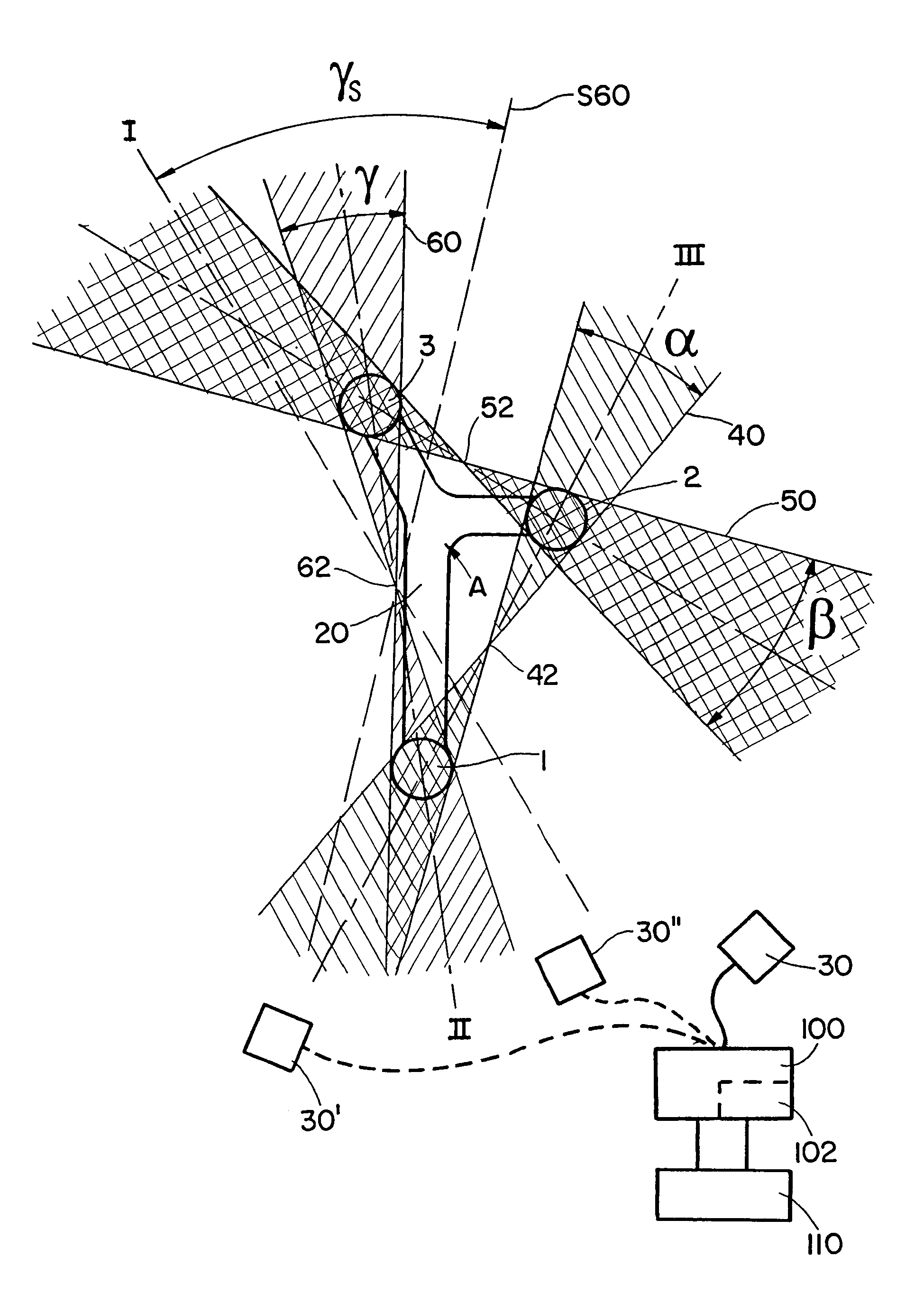
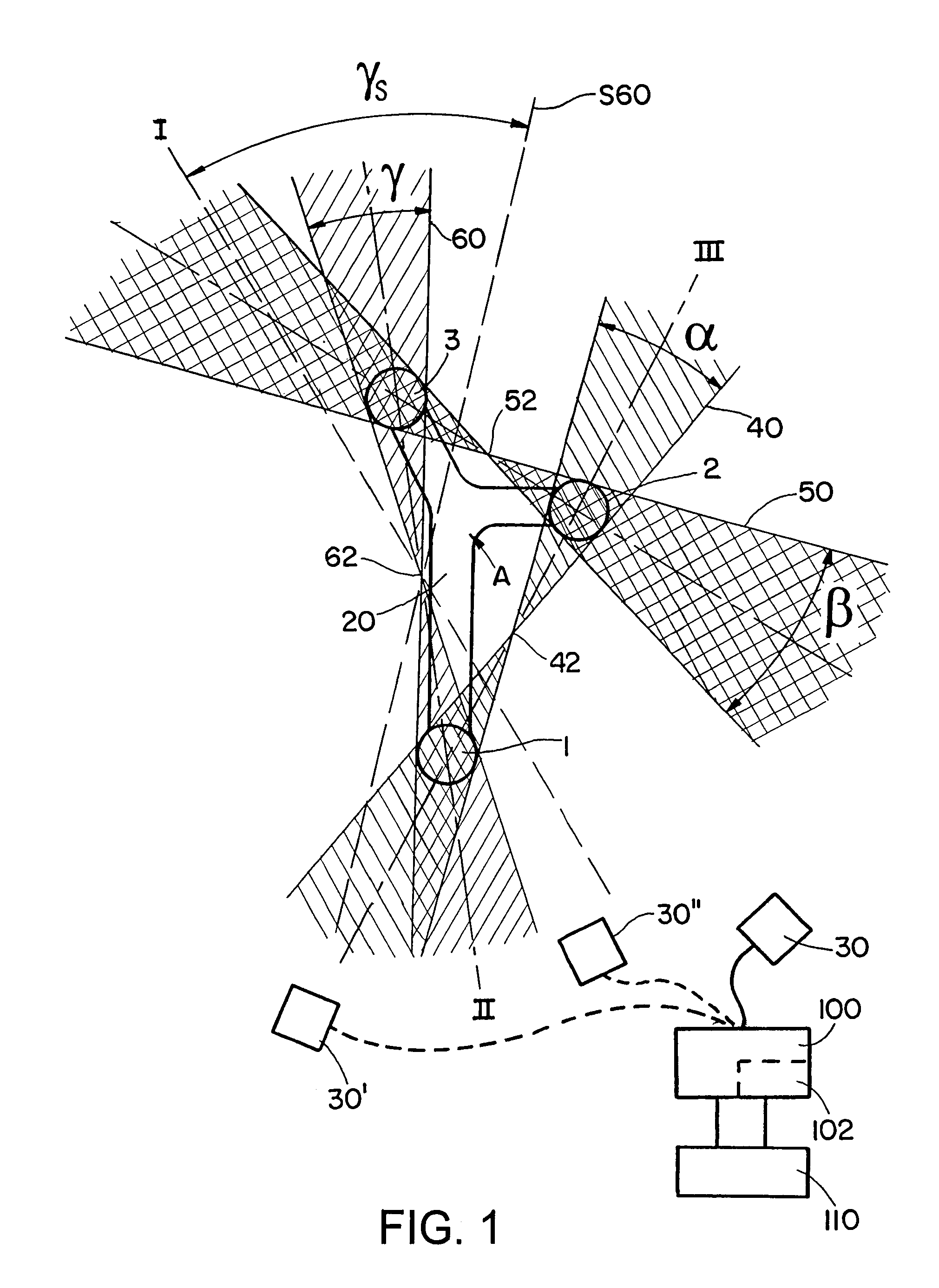
[0030]An exemplary marker navigation device is shown in FIG. 1 and comprises a reference star 20 with marker spheres 1, 2 and 3 connected by a bar A. The reference star 20 represents an example of a marker means. The marker spheres, which in the present example are passive marker spheres that do not emit radiation themselves but reflect radiation or waves, are detected by a detection means 30 (e.g., a camera or the like). Three example positions of the detection means 30 are indicated in FIG. 1. The first position is provided with the reference sign 30, the second position with the reference sign 30′, and the third position with the reference sign 30″.

[0031]Cone-shaped boundary surfaces bearing the reference signs 40, 50 and 60 surround the marker spheres 1, 2 and 3. The cone-shaped boundary surface 60 relates to the marker spheres 1 and 3, the cone-shaped boundary surface 40 relates to the marker spheres 2 and 1, and the cone-shaped boundary surface 50 relates to the marker spheres...


PUM


Abstract

A marker navigation device for determining and / or tracking a location of a marker device is provided. The marker device is attachable to an object, said marker device including a plurality of markers having known dimensions and being in a known positional relationship relative to each other. The marker navigation device includes: a detection device operative to detect signals emitted by or reflected from the plurality of markers, wherein the detection device is formed such that in first locations of the detection device relative to the marker device, detection of signals from one marker of the plurality of markers is restricted or impossible due to a location of another marker of the plurality of markers. In second locations of the detection device relative to the marker device, the plurality of markers are detectable by the detection device. The navigation device also includes a processing device communicatively coupled to the detection device and configured to calculate the first locations based on the relative locations of individual markers of the plurality of markers and based on the known dimensions of the plurality of markers, and calculate an actual location of the marker device relative to the detection device based on detected signals from at least one marker of the plurality of markers, the known locations of the plurality of markers relative to each other, and the known dimensions of the plurality of markers. The processing device also can determines whether the actual location of the marker device is one of the first locations. A warning device is communicatively coupled to the processing device and operative to output a warning signal when the actual relative location is one of the first relative locations.

Description

RELATED APPLICATION DATA[0001]This application claims priority of U.S. Provisional Application No. 60 / 862,878 filed on Oct. 25, 2006, which is incorporated herein by reference in its entirety.FIELD OF THE INVENTION[0002]The present application relates to a marker navigation device for detecting a marker means in a medical workspace, and determining a location of movable objects to which the marker means is attached.BACKGROUND OF THE INVENTION[0003]Currently, marker means are detected via a detection means (e.g., a camera or ultrasound detector). The marker means typically include three markers that are arranged in a fixed and predetermined location relative to each other and are in particular mechanically connected to each other. The markers attached to the marker means can be passive or active markers, wherein passive markers reflect waves and / or radiation emitted in their direction, and active markers are themselves the origin of the radiation and / or waves. The signals emitted fro...

Claims


Application Information

Patent Timeline
Patent Type & Authority Patents(United States)
IPC IPC(8): G08B1/08G01S3/02G08B5/22
CPCA61B19/52A61B19/5244A61B2019/5255A61B2017/00115A61B90/36A61B2034/2055A61B34/20
Inventor IMMERZ, MARTINTUMA, GREGOR
Owner BRAINLAB
Why Eureka
Try Eureka