
Process for automatic correction of the spectral inversion in a demodulator and device to implement the process

a technology of demodulator and process, which is applied in the direction of modulated carrier system, angle demodulation, transmission, etc., can solve the problems of not allowing data reception, spectral inversion is not difficult to manage, and inversion is not easy to corr

Active Publication Date: 2010-04-13
STMICROELECTRONICS SRL
View PDF2 Cites 3 Cited by
  • Summary
  • Abstract
  • Description
  • Claims
  • Application Information

AI Technical Summary

Problems solved by technology

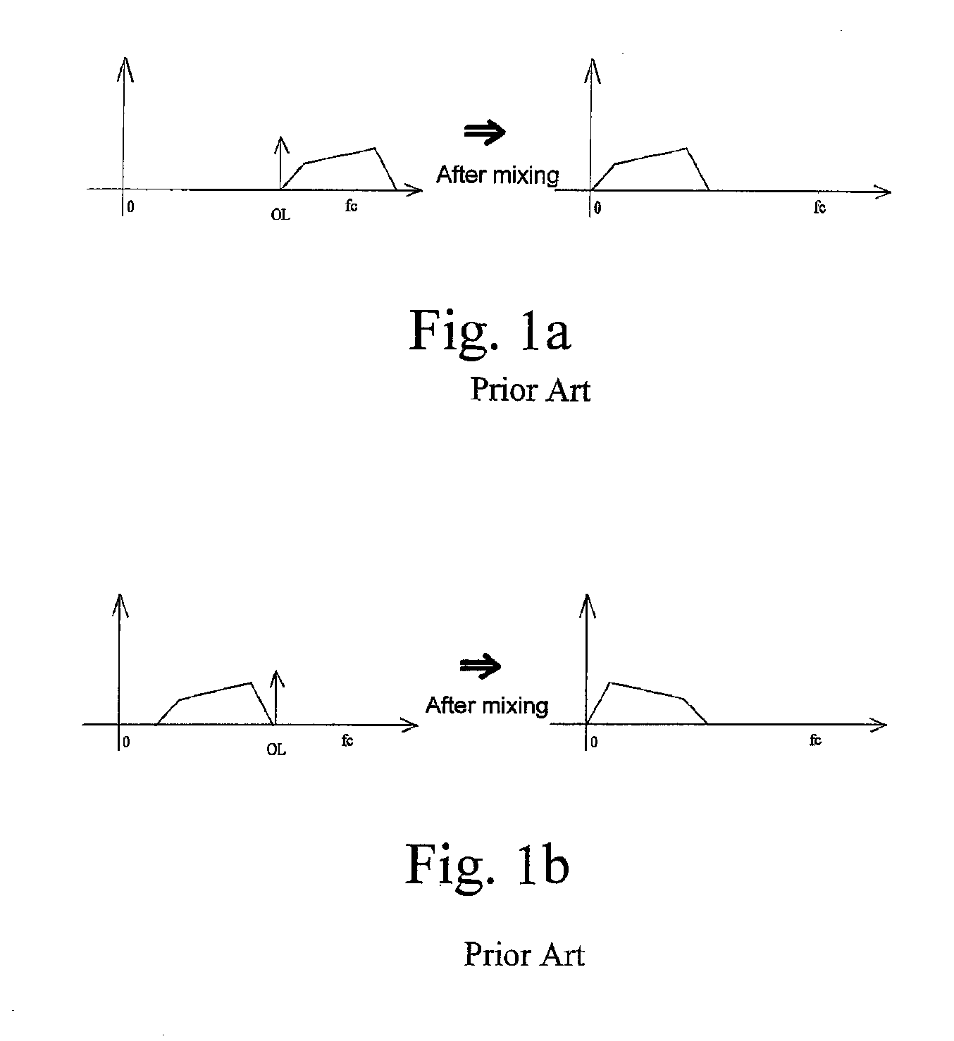
That inversion is not difficult to manage, especially when the spectrum of the signal to transmit is perfectly symmetric as is the case for an amplitude modulation.
On the other hand, when the modulation is more complex, a spectral inversion is a problem because data may not be detected.
However, this does not permit data reception when a spectral inversion occurs.
This mechanism, which is universally used, is satisfactory up to a certain point, but has the disadvantage of introducing a blocking latency time in the processing of the demodulated signal for most modern applications.

Method used


Image

  • Process for automatic correction of the spectral inversion in a demodulator and device to implement the process
  • Process for automatic correction of the spectral inversion in a demodulator and device to implement the process
  • Process for automatic correction of the spectral inversion in a demodulator and device to implement the process

Examples


Embodiment Construction

[0035]It should be understood that these embodiments are only examples of the many advantageous uses of the innovative teachings herein. In general, statements made in the specification of the present application do not necessarily limit any of the various claimed inventions. Moreover, some statements may apply to some inventive features but not to others. In general, unless otherwise indicated, singular elements may be in the plural and vice versa with no loss of generality.

[0036]The circuit as described above is part of the design for an integrated circuit chip. The chip design is created in a graphical computer programming language, and stored in a computer storage medium (such as a disk, tape, physical hard drive, or virtual hard drive such as in a storage access network). If the designer does not fabricate chips or the photolithographic masks used to fabricate chips, the designer transmits the resulting design by physical means (e.g., by providing a copy of the storage medium s...


PUM


Abstract

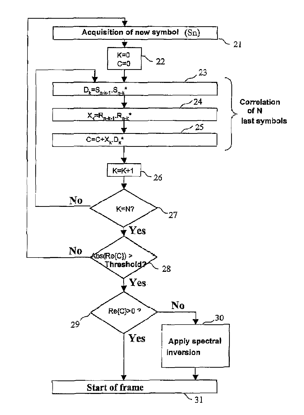
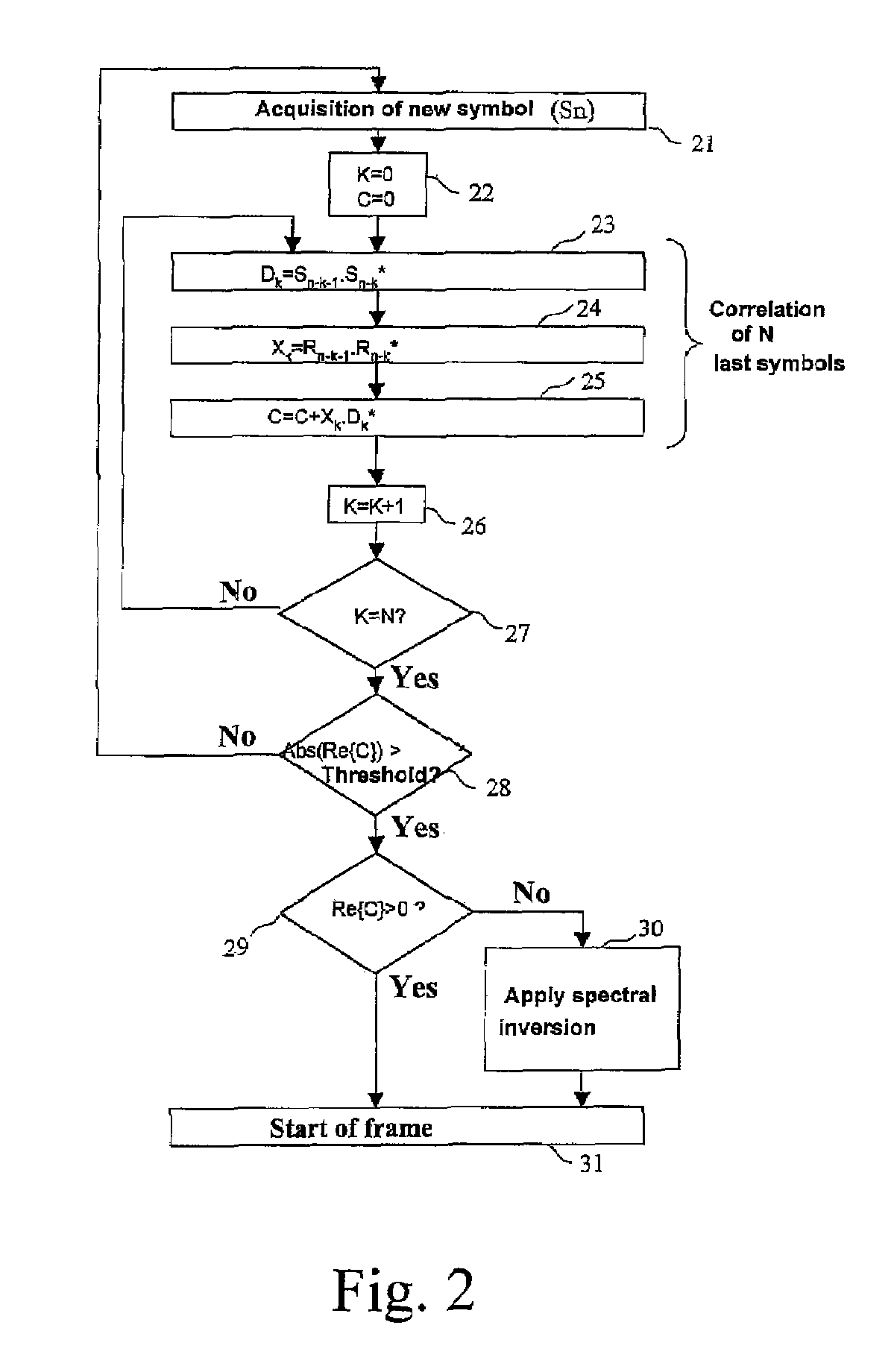
A process of correction of the spectral inversion for a receiver in a digital communication system: the process allows the reception in the receiver of a training sequence presumably known according to a modulation of type π / 2 BPSK or MDP2. The process includes the following steps: Demodulating of the training sequence; Calculating of the differential correlation on a set of N received samples (Rn) and presumably sent (Sn) to generate a result; Using the result to detect the beginning of the frame and to order a spectral inversion in the chain of reception of the aforementioned receiver before launching the detection of the beginning of the frame. A receiver to process automatically the spectral inversion is also described.

Description

CROSS-REFERENCE TO RELATED APPLICATIONS[0001]This application is based upon and claims priority from prior French Patent Application No. 05 07040, filed on Jul. 1, 2005 the entire disclosure of which is herein incorporated by reference.FIELD OF THE INVENTION[0002]The present invention generally relates to the filed of digital transmissions and more specifically to a process of automatic correction of spectral inversion in a demodulator of a digital transmission system.BACKGROUND OF THE INVENTION[0003]Digital communications show a significant development with mobile telephony, new digital television standards, and satellite transmissions. The significant progress in that domain and the great diversity of operators have made information a “good” as easy to exchange as goods can be.[0004]That great diversity of operators in the transmission chain has introduced the need, inside the decoder of the digital communication system, to detect, in addition to the classical parameters of time a...

Claims


Application Information

Patent Timeline
Patent Type & Authority Patents(United States)
IPC IPC(8): H04L27/14
CPCH03D3/00H04L27/2273H04L27/22
Inventor MEYER, JACQUES
Owner STMICROELECTRONICS SRL
Learn More