
Electronic damping for stage positioning

a technology of electronic damping and stage positioning, applied in the direction of printers, instruments, camera focusing arrangement, etc., can solve the problems of difficult to quickly and accurately move parts of the devices relative to one another, and small mechanical and electro-mechanical devices

Active Publication Date: 2010-04-13
DIGITALPTICS MEMS
View PDF4 Cites 27 Cited by
  • Summary
  • Abstract
  • Description
  • Claims
  • Application Information

AI Technical Summary

Benefits of technology

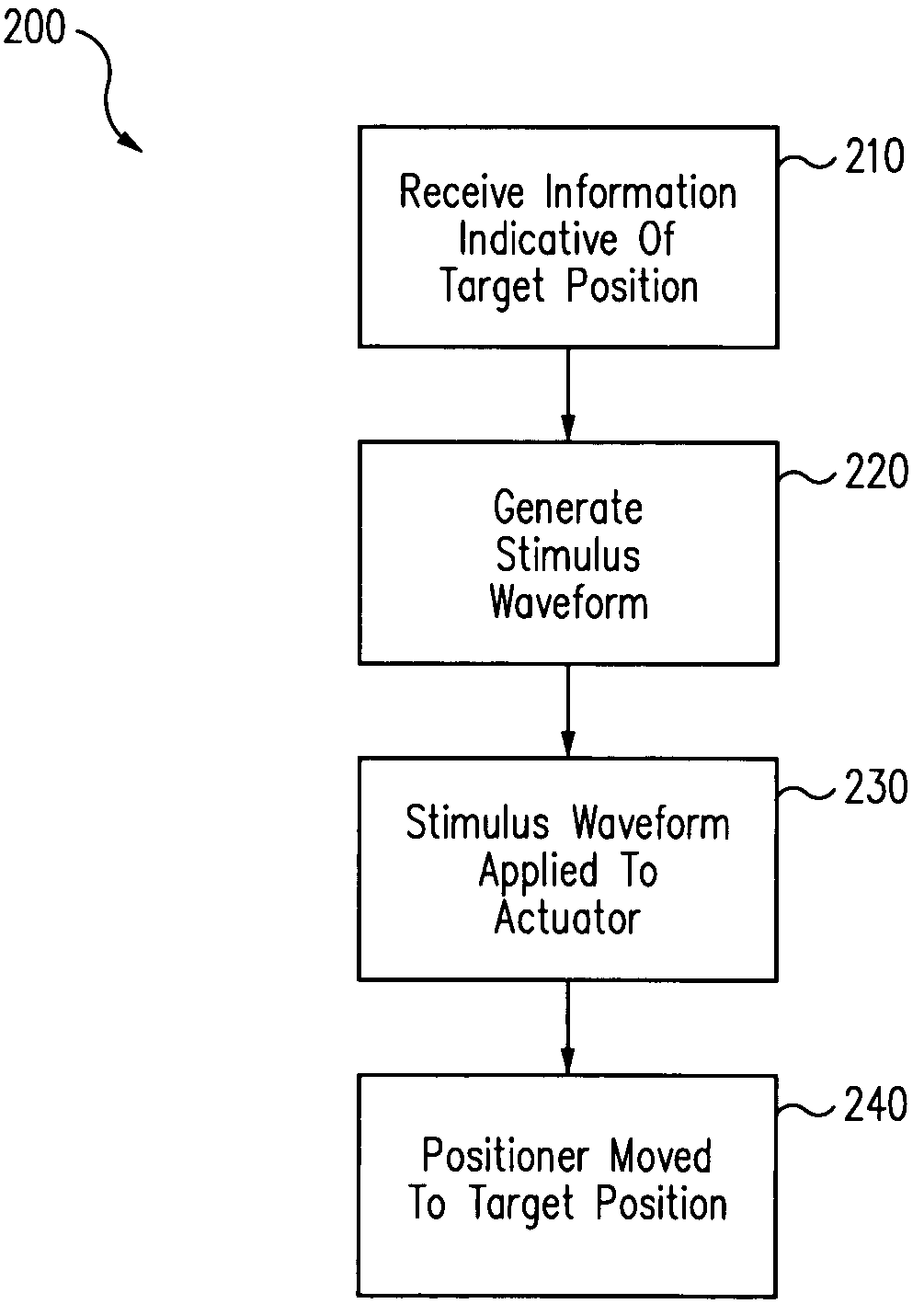
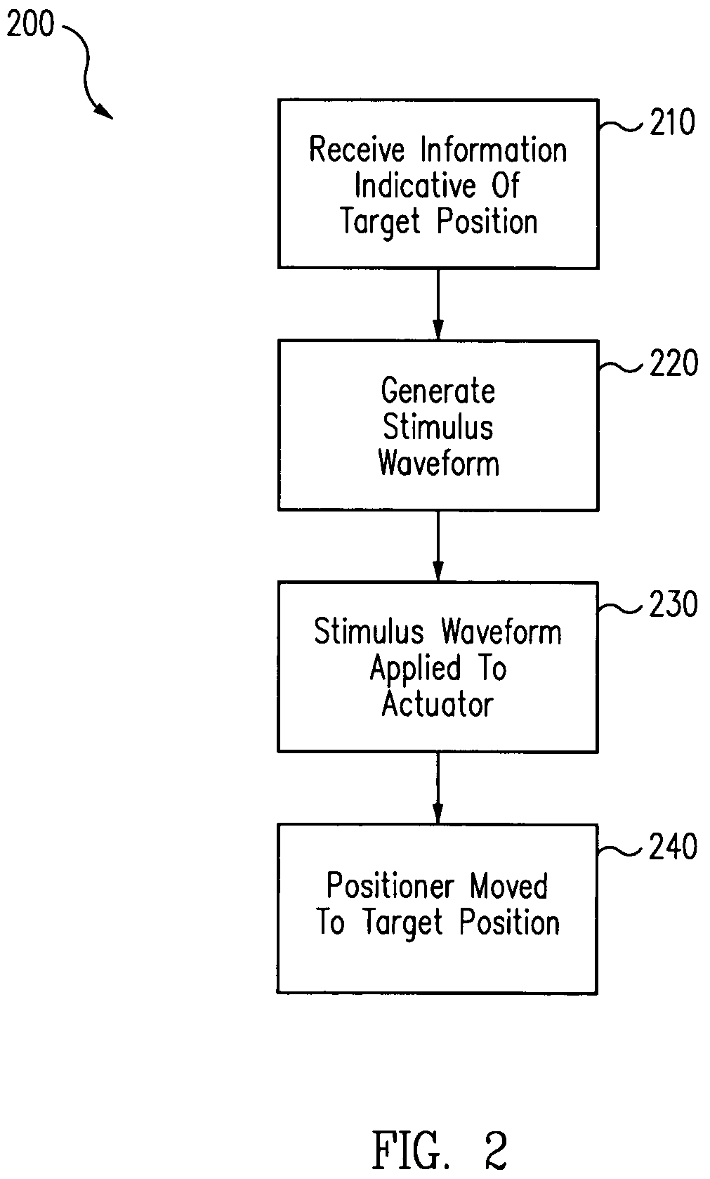
[0010]In general, in one aspect, a method of electronic damping includes receiving information indicative of a target position of a portion of a stage system included in a miniature electronic device. The target position is different than a current position of the portion of the stage system, and is included in a range extending from a minimum position to a maximum position. The stage system has at least one mechanical resonance frequency. The method further includes generating a waveform configured to move the portion of the miniature electronic device to the target position. The waveform includes one or more frequency components, but does not include the at least one mechanical resonance frequency. That is, the amplitude of a frequency component at the mechanical resonance frequency is substantially zero.

Problems solved by technology

However, small mechanical and electro-mechanical devices pose a number of challenges.
For example, it may be difficult to rapidly and accurately move parts of the devices relative to one another.
For example, camera-equipped cell phones were unheard of just a few years ago; now, they are a significant portion of the cell phone market.
However, available miniature cameras may not be optimal for some applications.
For example, available miniature cameras may not be optimal because they are fixed focus cameras (i.e., the focus of the cameras is pre-set).
However, the provided focus may be unacceptable for some applications.
Additionally, the relatively small aperture limits the light used to form the image.
This limitation may severely limit the camera's use in low light conditions.
However, the use of a flash consumes more power from the batteries, thus requiring more frequent battery charging.

Method used


Image

  • Electronic damping for stage positioning
  • Electronic damping for stage positioning
  • Electronic damping for stage positioning

Examples


Embodiment Construction

[0033]Systems and techniques provided herein provide improved device performance for small electro-mechanical devices incorporating one or more stage systems. A stage system includes a positioning stage and one or more actuators configured to apply a force (linear force and / or torque) to move the stage from a first position to a second position.

[0034]In some existing stage systems, a relatively large force may be applied by the actuator to the stage for a relatively short time, and then quickly reduced to zero. The force may be referred to as a step-function stimulus (although, as with all real physical systems, the applied force is not a pure step function).

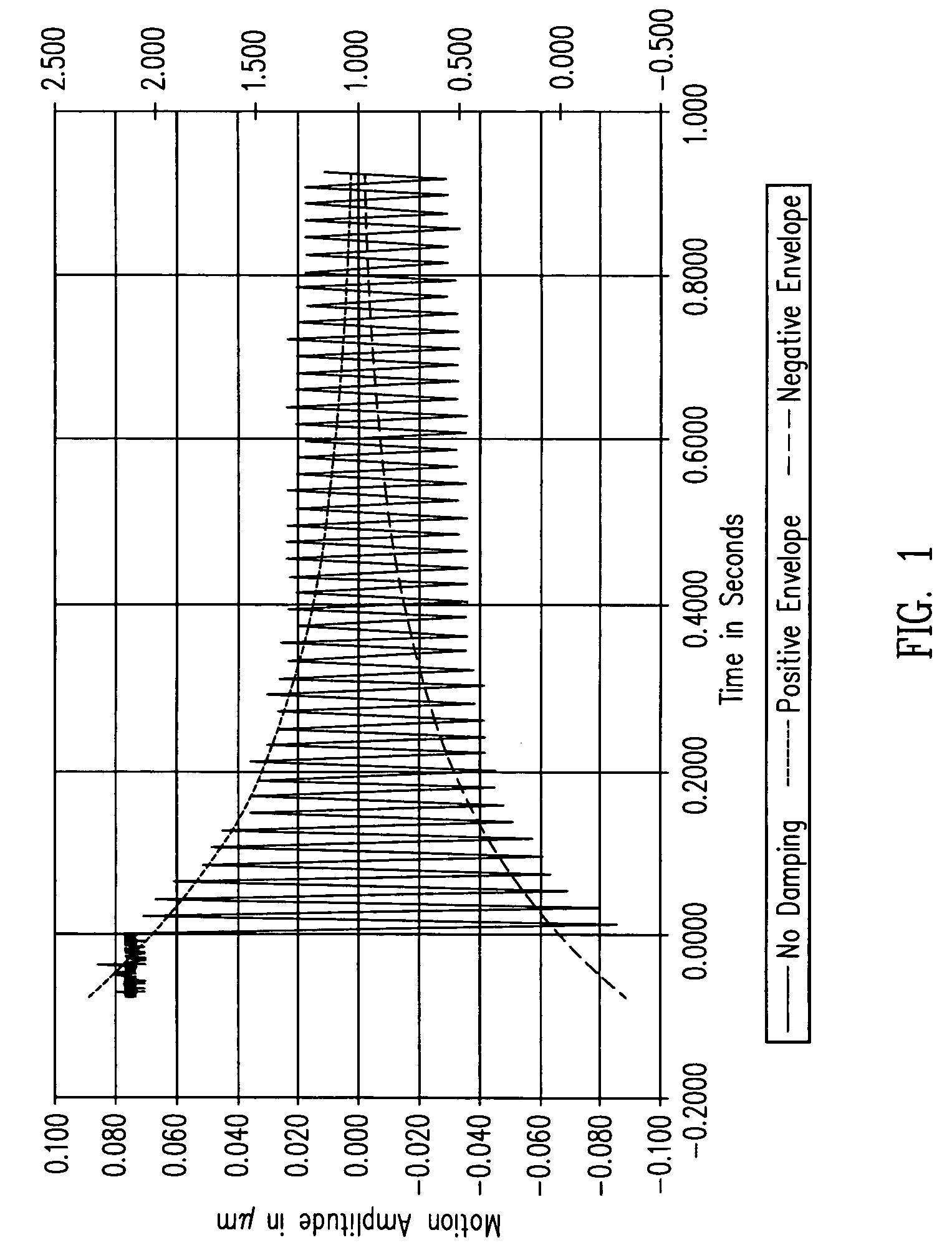
[0035]One problematic effect that may occur with actuator-induced movement of miniature device elements is ringing. Ringing, as discussed in further detail below with reference to FIG. 1, is the undesirable oscillation or vibration of a structure, such as a stage and the optics mounted thereon, that occurs after the structure ha...


PUM


Abstract

Systems and techniques for electro-magnetic damping in a stage system. An excitation waveform for one or more actuators includes one or more frequency components with associated amplitudes. Frequency components at a resonance frequency of the stage system have associated amplitudes that are substantially zero.

Description

CROSS-REFERENCE TO RELATED APPLICATIONS[0001]This patent application is a continuation in part of, and claims the benefit of the priority date of U.S. patent application Ser. No. 11 / 361,608, filed Feb. 24, 2006 and entitled AUTOFOCUS CAMERA, which is hereby incorporated by reference in its entirety, and also claims priority to U.S. Provisional Patent Application Ser. No. 60 / 713,971, filed Sep. 2, 2005, and entitled OPEN LOOP DAMPING, which is also hereby incorporated by reference in its entirety.BACKGROUND[0002]1. Field of Invention[0003]This invention generally relates to relative movement using small stages, such as stages for micro-electromechanical system (MEMS) devices.[0004]2. Related Art[0005]Improvements in fabrication processes for small devices (such as MEMS devices) are continuing to reduce minimum device sizes. However, small mechanical and electro-mechanical devices pose a number of challenges. For example, it may be difficult to rapidly and accurately move parts of the...

Claims


Application Information

Patent Timeline
Patent Type & Authority Patents(United States)
IPC IPC(8): G03B3/10G03B13/34G03B17/00
CPCG02B7/102H04N5/23212G03B17/02H04N23/67
Inventor GUTIERREZ, ROMAN C.RODRIGUEZ, ROBERTO J.LEANG, PAT K.
Owner DIGITALPTICS MEMS
Learn More