Sensing unit and method of making same

a technology of sensing unit and sensing unit, which is applied in the direction of speed/acceleration/shock measurement, measurement devices, instruments, etc., can solve the problems of increasing the number of components and a more complicated structure, and achieves the reduction of the cost of making the sensing unit, simple constitution, and small number of components

Active Publication Date: 2010-04-20
HEADWAY TECH INC +1
View PDF5 Cites 70 Cited by
  • Summary
  • Abstract
  • Description
  • Claims
  • Application Information

AI Technical Summary

Benefits of technology

[0007]However, when sensor portions are provided in a conventional sensing unit such as that described above, wiring must be provided for each sensor portion, leading to an increase in the number of components and a more complicated structure.
[0010]In this sensing unit, the spring portion having the support portion and the movable portion is conductive, and a signal of the sensor portion provided on the movable portion of the spring portion is transmitted via the spring portion. Hence, the sensing unit according to the present invention has a simple constitution with a small number of components, and a wire does not necessarily have to be provided for each sensor portion. As a result, a reduction in manufacturing cost, simplification of the manufacturing process, and so on are achieved.
[0017]In this method of making a sensing unit, the conductive spring portion is formed by plating. The sensor portion for transmitting signals via the spring portion is formed in the part of the spring portion that is to become the movable portion. Hence, according to the method of making a sensing unit of the present invention, there is no need to provide a wire for each sensor portion, and a sensing unit having a simple constitution and a small number of components can be obtained. As a result, a reduction in the cost of making the sensing unit, simplification of the manufacturing process, and so on are achieved.

Problems solved by technology

However, when sensor portions are provided in a conventional sensing unit such as that described above, wiring must be provided for each sensor portion, leading to an increase in the number of components and a more complicated structure.

Method used


Image

  • Sensing unit and method of making same
  • Sensing unit and method of making same
  • Sensing unit and method of making same

Examples


first embodiment

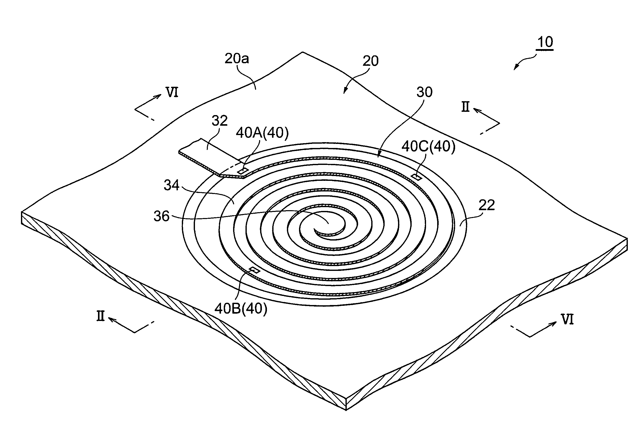
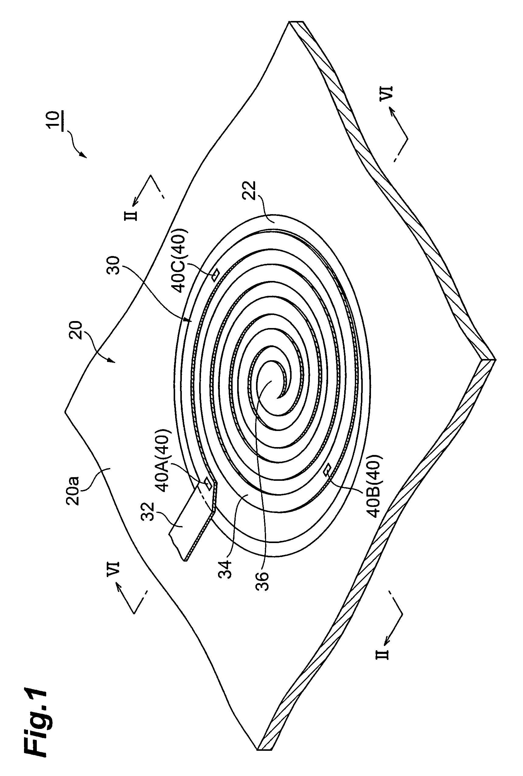
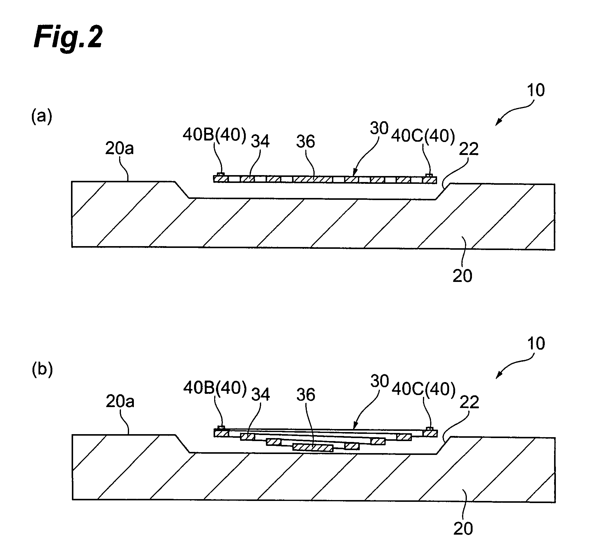
[0031]FIG. 1 is a schematic perspective view showing a sensing unit 10 according to a first embodiment of the present invention. FIG. 2 is a sectional view taken along a line II-II of the sensing unit 10 shown in FIG. 1, (a) showing a non-elongated state and (b) showing an elongated state. As shown in FIGS. 1 and 2, the sensing unit 10 comprises a substrate 20 and a spring portion 30 provided on the substrate 20.

[0032]The substrate 20 is formed from Al2O3, for example, and a surface 20a thereof is flat. A hole (recessed portion) 22 having a substantially circular cross-section is provided in the surface 20a of the substrate 20. The depth of the hole 22 is set at approximately 0.5 to 3.0 μm when shallow, and approximately 3.0 to 10 μm when deep, for example.

[0033]The spring portion 30 is a thin film member extending parallel to the substrate surface 20a of the substrate 20, and is formed by subjecting a conductive material such as Cu or Ni to plating. The spring portion 30 is constit...

second embodiment

[0060]Next, a sensing unit 10A according to a second embodiment of the present invention will be described. FIG. 7 is a schematic plan view showing the sensing unit 10A.

[0061]As shown in FIG. 7, in the sensing unit 10A, two seating portions 24 (having a height of approximately 0.5 to 10 μm, for example) are provided on a substrate 20A, and a conductive spring portion 30A straddles the two seating portions 24. Similarly to the spring portion 30 described above, the spring portion 30A is a thin film member extending parallel to the substrate surface 20a of the substrate 20A, and is formed by subjecting a conductive material such as Cu or Ni to plating.

[0062]The spring portion 30A is constituted by a pair of support portions 32 provided on the seating portions 24 of the substrate 20A, and a movable portion 34 positioned therebetween. Hence, the formation region (first region) of the movable portion 34 of the spring portion 30A is lower than the formation region (second region) of the s...

third embodiment

[0071]Next, a sensing unit 10B according to a third embodiment of the present invention will be described. FIG. 9 is a schematic plan view showing the sensing unit 10B.

[0072]As shown in FIG. 9, the sensing unit l0B has a similar constitution to the sensing unit l0A described above, and a spring portion 30B of the sensing unit l0B is formed by subjecting a conductive material to plating, similarly to the spring portions 30 and 30A. In the sensing unit l0B, the seating portions 24 of a substrate 20B are arranged in a Y direction orthogonal to the aforementioned X direction. The central portion 34a of the movable portion 34 of the spring portion 30B extends along a virtual line L2 parallel to the arrangement direction (Y direction) of the pair of support portions 32 provided on the seating portions 24. Hence, in the spring portion 30B of this sensing unit l0B, the central portion 34a of the movable portion 34 is supported so as to be capable of oscillating in the arrangement direction ...


PUM

PropertyMeasurementUnit
depthaaaaaaaaaa
depthaaaaaaaaaa
depthaaaaaaaaaa

Abstract

In a sensing unit according to the present invention, a spring portion having a support portion and a movable portion is conductive. A signal of a sensor portion provided on the movable portion of the spring portion is transmitted via the spring portion. Hence, the sensing unit according to the present invention has a simple constitution with a small number of components, and a wire does not necessarily have to be provided for each sensor portion. As a result, a reduction in manufacturing cost, simplification of the manufacturing process, and so on are achieved.

Description

BACKGROUND OF THE INVENTION[0001]1. Field of the Invention[0002]The present invention relates to a sensing unit and a method of making the sensing unit.[0003]2. Description of the Related Art[0004]A silicon acceleration sensor employing MEMS technology is known from the prior art as an acceleration sensor (accelerometer).[0005]A sensing unit of this silicon acceleration sensor is typically made through a process such as that shown in FIG. 11. More specifically, when making a sensing unit 110 of the silicon acceleration sensor, first, as shown in (a) of FIG. 11, a photomask 102 having a pattern of stripes arranged in parallel is formed on a silicon substrate 100. Deep etching (at an etching depth of 25 to 30 μm) using the photomask 102 is then performed, thereby forming a plurality of parallel trenches 104. Then, as shown in (b) of FIG. 11, an SiO2 film 106 is deposited on an upper surface of the substrate 100 and an inner wall surface of the trenches 104. Next, as shown in (c) of FI...

Claims


Application Information

Patent Timeline
Patent Type & Authority Patents(United States)
IPC IPC(8): G01P15/10G01P15/11G01P15/12G01P15/18
CPCG01P15/08G01P15/0802G01P15/105Y10T29/49176Y10T29/49002Y10T29/49146Y10T29/4922Y10T29/4913Y10T29/49007Y10T29/49171
Inventor SASAKI, YOSHITAKASHIMIZU, TATSUSHIHORINAKA, TAKEHIROISHIZAKI, KAZUOTANEMURA, SHIGEKI
Owner HEADWAY TECH INC
Why Eureka
Try Eureka