Magnetic head for reading data

a data and magnetic head technology, applied in the direction of head placement, sensing record carriers, instruments, etc., can solve the problem of inadmissible act, and achieve the effect of preventing wire disconnection

Inactive Publication Date: 2010-04-20
TECHRECO
View PDF14 Cites 19 Cited by
  • Summary
  • Abstract
  • Description
  • Claims
  • Application Information

AI Technical Summary

Benefits of technology

[0014]According to the present invention, an external connection terminal is provided inside the magnetic head and connected to a signal conductor at the location. Thus, even if a third person tries to steal card data from the magnetic head, a terminal of a data acquisition device cannot be connected to the external connection terminal without disassembling the magnetic head. Therefore, it is very difficult for a third person to acquire card data from the magnetic head for nefarious purposes.
[0015]In conventional magnetic heads, a rod-shaped terminal is used as an external connection terminal. Thus, when a signal conductor is attached to the rod-shaped terminal by soldering in a post-step in the factory or in an attaching process after shipping, a soldered part of an electric wire may be melted by heat from the iron and heat conduction to break the electrical contact therebetween or the rod-shaped terminal may be bent by the pressure from the worker's thumbs and fingers applied thereto during soldering, resulting in a wire disconnection under the tension in a processed portion which has been fixed. However, according to the magnetic head of the present invention, since the terminal connecting portion is away from the opening and since the external connection terminal is located inside the sealed case and fixed by the resin, no stress is exerted on the connecting portion between the external connection terminal and the electric wire. Thus, the wire disconnection can be prevented.
[0016]According to the invention, if desired, a flexible wiring substrate is used as the signal conductor, and the flexible wiring substrate is formed by a signal conductor layer sandwiched between protective layers each having short-circuit detection screen. Thus, if a third person scratches the flexible wiring substrate with the tip of a drill or the like when he or she tries to connect to a conductive line on the signal conductor layer in order to acquire card data on a credit card, the tip of the drill or the like breaks a conductive line on the signal conductor layer sandwiched between the protective layers and contacts the short-circuit detection screen of the upper or lower protective layer to cause a change in impedance or a short-circuit between the short-circuit detection screens. Then, a signal is transmitted to a short-circuit detection circuit provided separately and the abnormal condition is detected. It is, therefore, very difficult to acquire card data.
[0017]According to the invention, if desired, the signal conductor layer of the flexible wiring substrate may be composed of a plurality of layers and all or some of the conductive lines are dispersed on the layers of the signal conductor layer. Thus, since the signal lines are arranged in a three-dimensional fashion as well as in a two-dimensional fashion, the wiring pattern is so complicated that it is difficult for a third person to contact the conductive lines of the signal conductor for nefarious purposes.
[0018]In addition, according to the invention, if desired, dummy lines are provided adjacent to some of the conductive lines of the signal conductor layer, the wiring pattern is so complicated that it is difficult for a third person to contact the conductive lines of the signal conductor for nefarious purposes.
[0019]Further, according to the invention, if desired, a plurality of pairs of twisted pair wires may be used as the signal conductor, first ends of each pair of twisted pair wires are connected to the external connection terminals of different bobbins, and the pairs of twisted pair wires are woven together. Therefore, the wiring pattern of the signal conductor is so complicated that a third person cannot easily recognize the precise wiring pattern of the signal conductor. As a result, it is difficult for a third person to contact the conductive lines of the signal conductor for nefarious purposes.DETAILED DESCRIPTION OF THE PREFERRED EMBODIMENTS

Problems solved by technology

Naturally, such an act is not permissible.

Method used


Image

  • Magnetic head for reading data
  • Magnetic head for reading data
  • Magnetic head for reading data

Examples


first embodiment

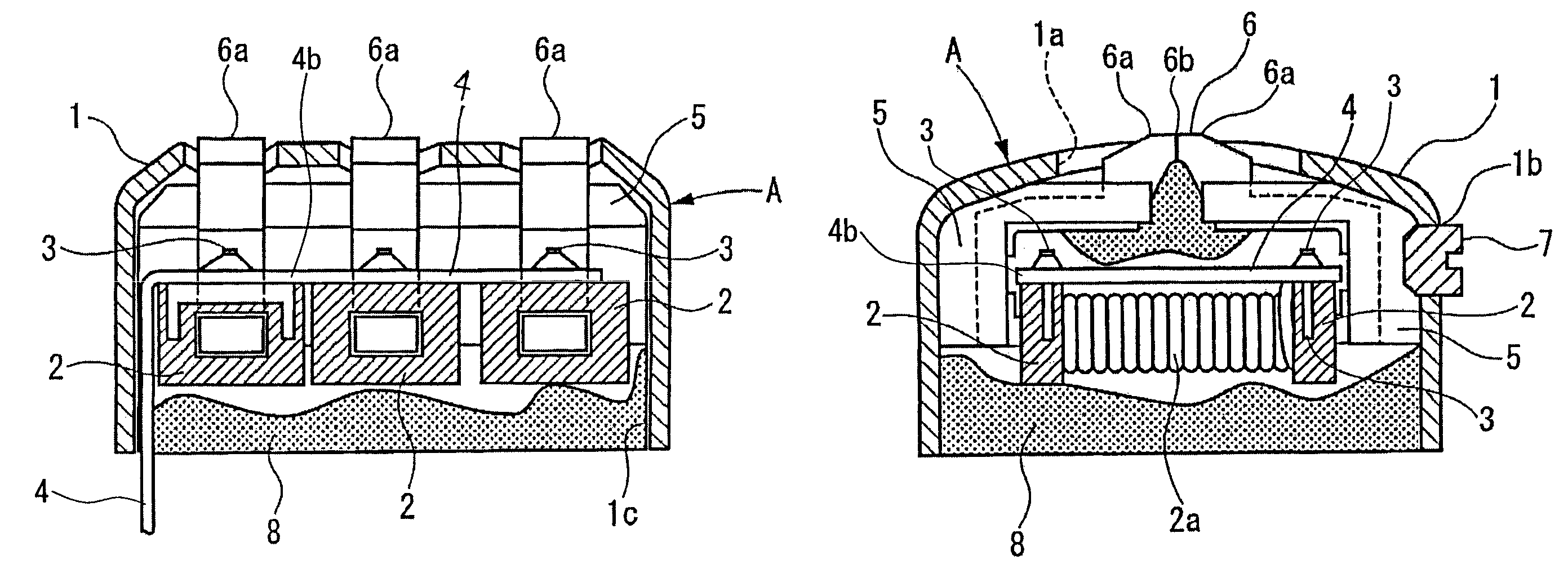
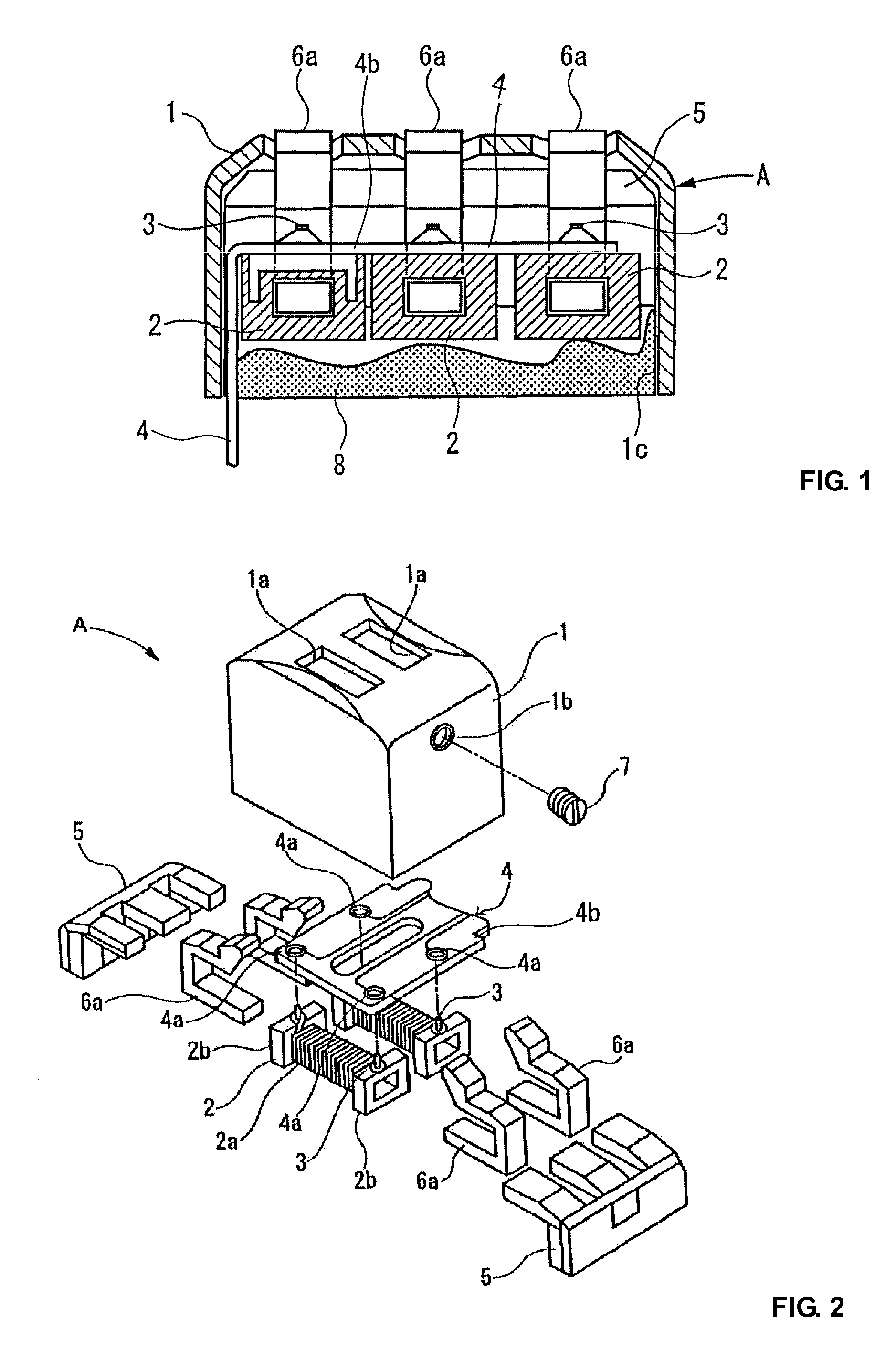
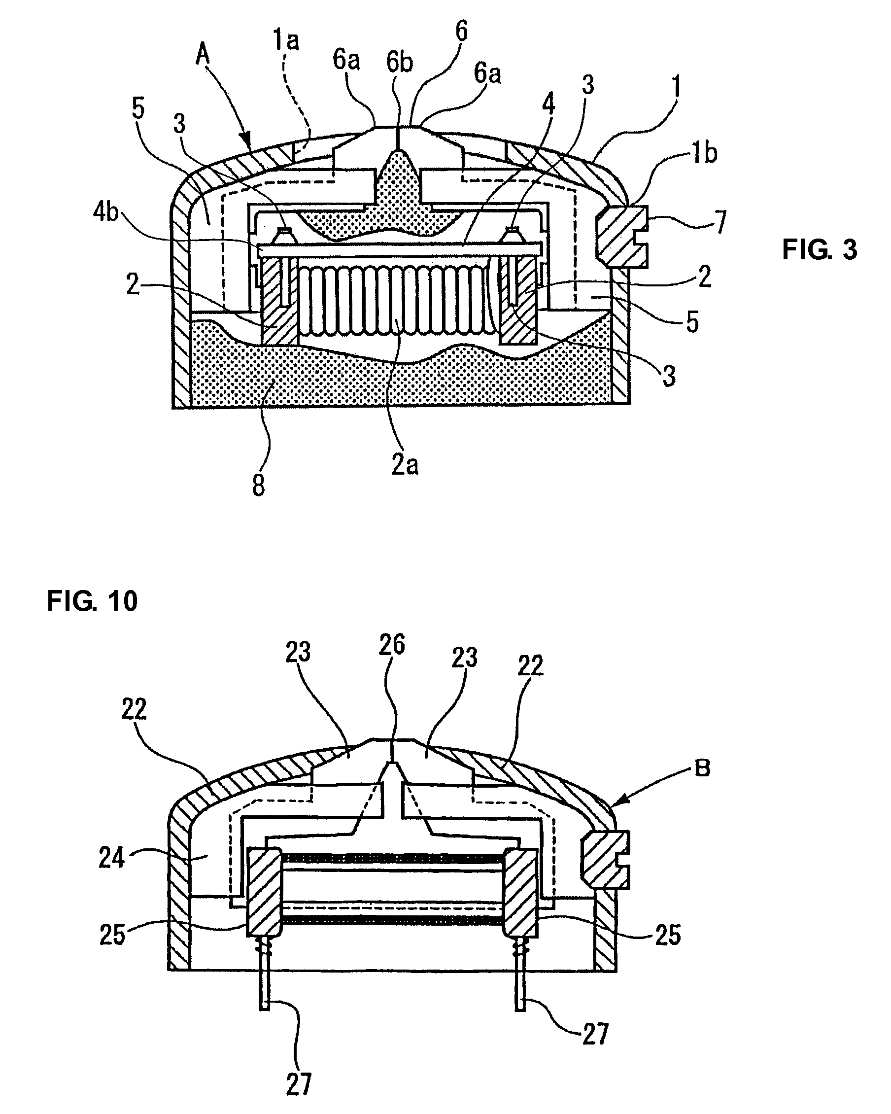
[0031]Description is hereinafter made of an embodiment of the present invention with reference to the drawings. FIG. 1 is a cross-sectional side view of a magnetic head according to the present invention. FIG. 2 is an exploded perspective view illustrating the configuration of the magnetic head according to the present invention. FIG. 3 is a cross-sectional front view of the magnetic head of the present invention.

[0032]As shown in FIGS. 1, 2 and 3, a magnetic head A according to one embodiment of the present invention has a plurality of bobbins 2, each with an electric wire 2a wound thereon, arranged with their longitudinal axes horizontal in a generally rectangular box-shaped sealed case 1 having an open bottom (the numbers of the bobbins 2 arranged are different between FIG. 1 and FIG. 2). Each bobbin 2 has flanges 2b at opposite ends, and terminal pins 3 as external connection terminals provided opposite each other on upper surfaces of the flanges 2b. The terminal pins 3 are conn...


PUM


Abstract

A magnetic head of a credit card identification terminal for reading card data which can prevent card data from being illegally acquired. The magnetic head includes a generally box-shaped sealed case having an open side; a bobbin with an electric wire wound thereon provided in the sealed case; a core member extending from the bobbin and having an end protruding to the outside of the sealed case through a through-hole formed through a side of the sealed case opposite the opening; a terminal pin connected to the wire wound on the bobbin; and resin filled in the hollow space in the sealed case, the terminal pin is embedded in the resin filled in the sealed case, one end of a flexible wiring substrate is connected to the terminal pin, and the other end of the flexible wiring substrate extends to the outside of the sealed case from the opening.

Description

CROSS-REFERENCE TO RELATED APPLICATIONS[0001]The present application claims priority from Japanese Patent Application No. 2007-118577, filed Apr. 27, 2007 and Japanese Patent Application No. 2007-272187, filed Oct. 19, 2007, both incorporated herein by reference in their entirety.FIELD OF THE INVENTION[0002]The present invention relates to a magnetic head of a credit card identification terminal for reading card data which can prevent card data from being illegally acquired therefrom and through a signal conductor originating therefrom. In particular, the present invention relates to a magnetic head for a card reader which reads a signal from a magnetic card as a medium, and more particularly, to a magnetic head having a function of preventing skimming theft of card data by an illegal method.BACKGROUND OF THE INVENTION[0003]In recent years, because of widespread use of the magnetic cards as credit cards, payments for purchases are often made by credit cards. More specifically, when ...

Claims


Application Information

Patent Timeline
Patent Type & Authority Patents(United States)
IPC IPC(8): G06K7/08
CPCG06K7/083G11B5/488G11B5/4853
Inventor HORIGUCHI, MASAOOHSAKA, MINORU
Owner TECHRECO
Why Eureka
Try Eureka