Oil scavenge system for gas turbine engine bearing cavity

a gas turbine engine and oil scavenging technology, applied in the direction of bearings, shafts, engine lubrication, etc., can solve the problems of unwanted situation, insufficient gravity return of oil,

Active Publication Date: 2010-04-20
PRATT & WHITNEY CANADA CORP
View PDF11 Cites 21 Cited by
  • Summary
  • Abstract
  • Description
  • Claims
  • Application Information

AI Technical Summary

Problems solved by technology

Scavenging of the oil is accordingly quite important and return of the oil by gravity is insufficient for prescribed requirements.
This limitation is also exacerbated by the fact that the oil cannot exceed the level of the maximum permissible cavity oil level or the oil will leak through the seals into surrounding area, creating an unwanted situation.

Method used


Image

  • Oil scavenge system for gas turbine engine bearing cavity
  • Oil scavenge system for gas turbine engine bearing cavity
  • Oil scavenge system for gas turbine engine bearing cavity

Examples


Embodiment Construction

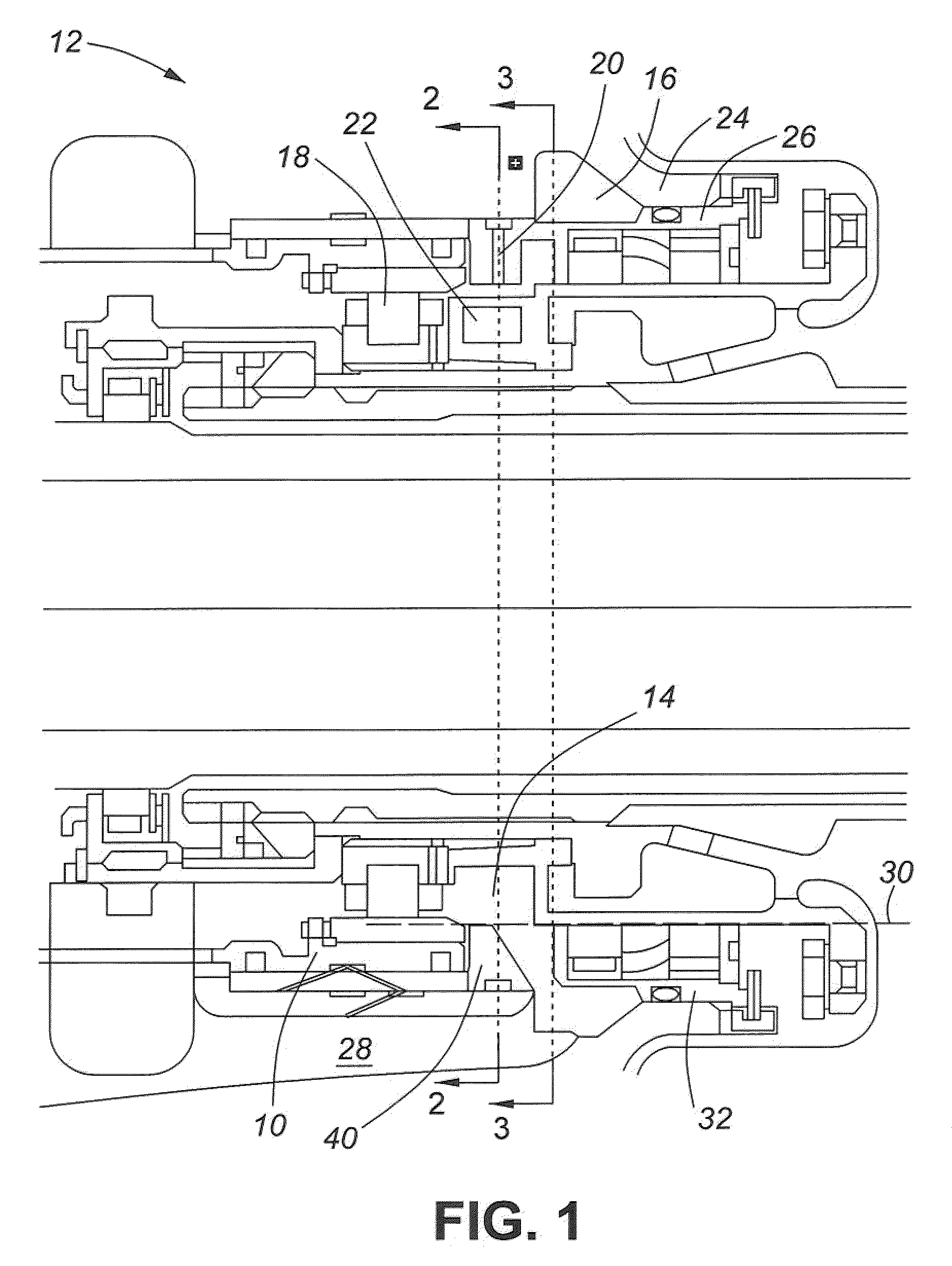
[0013]Referring to FIG. 1, shown is a cross section of a bearing housing 10, within a gas turbine engine, generally denoted by numeral 12 as bearing cavity.

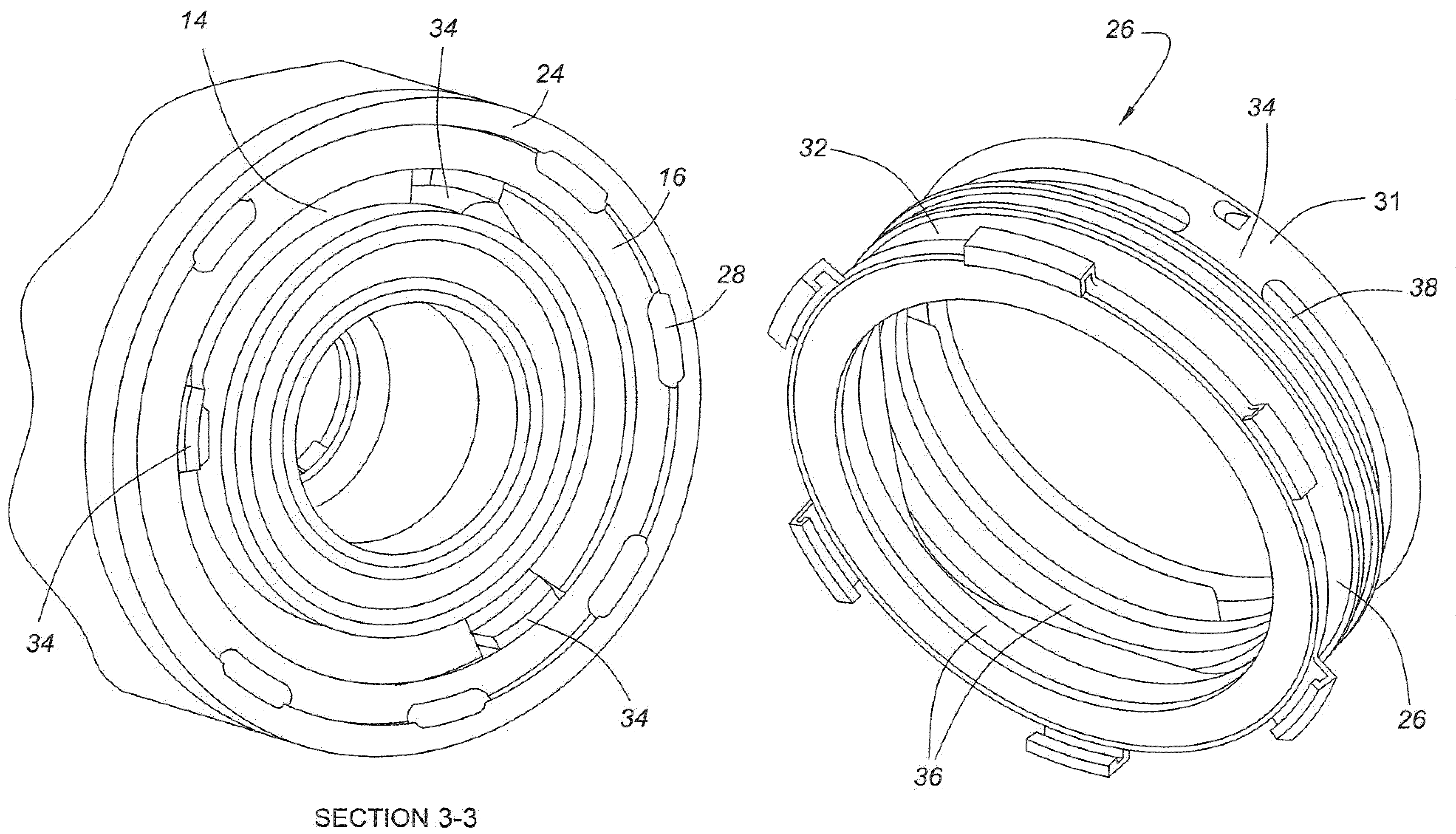
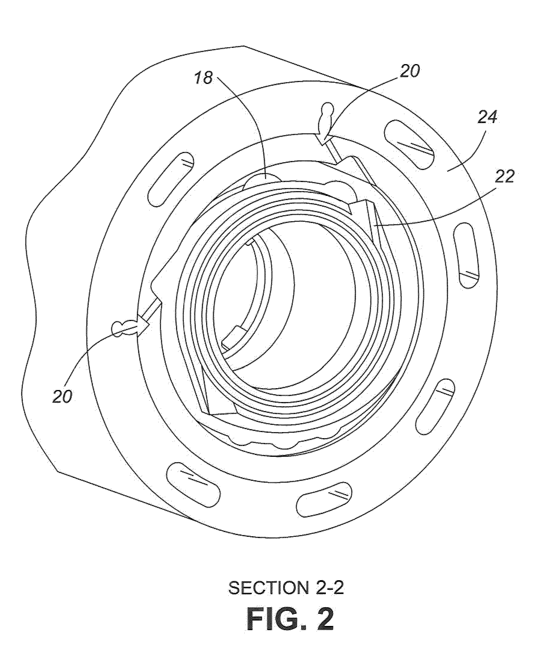
[0014]Referring to the remaining Figures collectively, the bearing cavity 12, is composed of two coaxial cavities 14 and 16, respectively. Cavity 14, the inner cavity, is an active cavity and it is where the bearing 18 is located. Oil jets 20 are positioned radially and substantially peripherally of the housing 10 to supply oil to the bearing 18. The jets 20 are static and distribute the oil from a source thereof and particularly to rotating oil scoops 22. The scoops 22 capture the oil and direct it to the bearing 18.

[0015]Turning now to the outer cavity 16, the latter is bounded by the outer case 24 and a carbon seal housing 26. A plurality of radially arranged oil scavenging apertures 28 are disposed coaxially about the bearing 18 and connect, for fluid communication, the outer cavity 16 with the remainder of the oil system of ...


PUM


Abstract

An oil scavenging system and method suitable for use in a gas turbine engine having a bearing housing. The bearing housing provides for arcuate slots within the housing and a plurality of peripherally arranged apertures disposed for cooperation with the arcuate slots. During rotation of the bearing and shaft, the rotational momentum induces rotation of the oil which distributes the oil to the peripheral circumference of the housing for eventual passage through the slots and apertures. The arrangement maximizes the use of the circumferential space of the bearing for efficient oil distribution.

Description

TECHNICAL FIELD[0001]The invention relates generally to an oil scavenging system and method and, more particularly, to an improved oil scavenging system and method for use in a gas turbine engine.BACKGROUND OF THE ART[0002]The bearing cavity of a gas turbine engine houses the bearing which requires a vast amount of oil for ensuring proper lubrication and heat dissipation for the bearing. Scavenging of the oil is accordingly quite important and return of the oil by gravity is insufficient for prescribed requirements. This limitation is also exacerbated by the fact that the oil cannot exceed the level of the maximum permissible cavity oil level or the oil will leak through the seals into surrounding area, creating an unwanted situation.[0003]Accordingly, there is a need to provide an improved oil circulation system for a gas turbine engine not so limited as present arrangements.SUMMARY OF THE INVENTION[0004]It is therefore an object of this invention to provide an improved oil distrib...

Claims


Application Information

Patent Timeline
Patent Type & Authority Patents(United States)
IPC IPC(8): F16C33/66
CPCF01D25/18F16C35/042F16C33/6685F05D2260/602F16C2360/23
Inventor BLAIS, DANIEL
Owner PRATT & WHITNEY CANADA CORP
Why Eureka
Try Eureka