Process for casting oil distribution disc of vane pump

A technology of casting blades and oil distribution plates, which is applied in the direction of manufacturing tools, casting molding equipment, casting molds, etc., can solve the problems of affecting the smoothness of oil passages, increasing the noise of vane pumps, and the number of molds, etc., achieving significant economic benefits and social benefits Benefits, improve product quality, improve the effect of casting quality

Active Publication Date: 2010-07-21
SHANXI SCENERY MACHINE MFG
View PDF3 Cites 17 Cited by
  • Summary
  • Abstract
  • Description
  • Claims
  • Application Information

AI Technical Summary

Problems solved by technology

There are problems in this process: 1. The assembling and bonding part is in the oil passage cavity, and the dimensional accuracy of the oil window is difficult to guarantee; 2. The bonding part is draped in the oil passage cavity, which is not easy to polish and affects the smoothness o

Method used


Image

  • Process for casting oil distribution disc of vane pump
  • Process for casting oil distribution disc of vane pump
  • Process for casting oil distribution disc of vane pump

Examples


Embodiment 1

[0043] Embodiment 1: This embodiment is the casting of PFX21 oil distribution plate, including process design, mold design and manufacture, core making, sand core assembly, modeling, pouring, and sand cleaning. This embodiment consists of 1#, 2#, and 3# sand The core and the 145 molding machine plate are composed, and the specific steps are as follows:

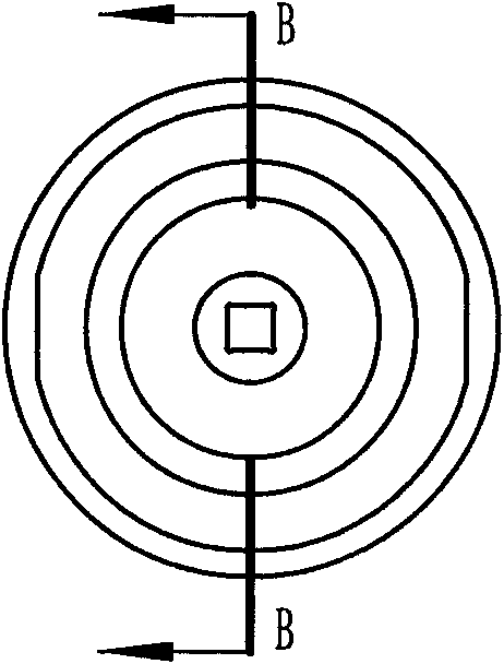
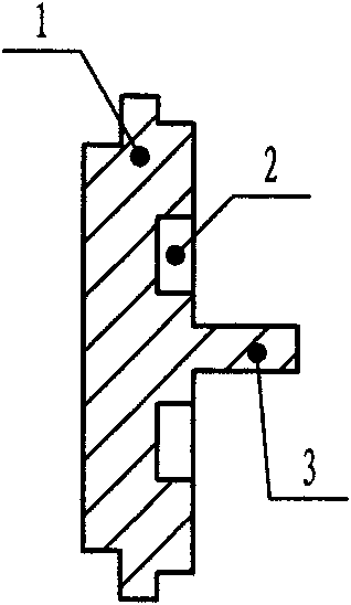
[0044] 1. Process design: Determine the process plan, use coated sand to make the core, and make a thin-shell sand core. All castings are made in the sand core, and the sand core is placed in the green mold sand cavity for pouring; design according to the part drawing casting process, Figure 9 As shown, the inner cavity of the oil passage of the part is conical, that is, one end of the oil passage has a larger aperture, and the other end has a smaller aperture (the factory term is called dovetail shape, that is, the shape of the sand core of the oil passage is dovetail shape, and one end of the sand core is wider. , the othe...

Embodiment 2

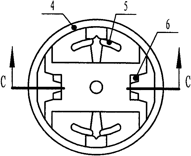
[0052] Embodiment 2: This embodiment is the casting method of PFX3-07 oil distribution plate. The process steps are the same as in Embodiment 1. The difference is that a total of 6 sand cores are required, that is, 1 main body sand core and 2 independent Dovetail sand core, 2 filling sand cores and 1 cover plate sand core, the shaft hole sand core and the main sand core are blown together, the two dovetail oil passages are made separately, and the independent dovetail sand core is bonded The sand filling agent is bonded to the chassis of the main sand core, and the sand filling sand core is composed of 2 small sand cores, which are molded with a 145 molding machine, with 4 pieces in one mold.

Embodiment 3

[0053] Embodiment 3: This embodiment is the casting method of PFX4-07 oil distribution plate. Its process steps are the same as in Embodiment 1. The difference is that a total of 6 sand cores are required, that is, 1 main body sand core and 2 independent Dovetail-shaped sand core, 2 independent ordinary oil passage sand cores and 1 cover plate sand core, the dovetail sand core is made separately and bonded to the cover plate sand core by adhesive, two ordinary oil passage sand cores They are independently blown and called independent ordinary oil channel sand cores, and are bonded to the cover plate sand cores by adhesives. They are molded with a 145 molding machine, and there are 4 pieces in one mold.


PUM

PropertyMeasurementUnit
Side wall thicknessaaaaaaaaaa
Thicknessaaaaaaaaaa
Granularityaaaaaaaaaa

Abstract

The invention relates to a process for a casting oil distribution disc of a vane pump, which belongs to the precision casting production process of hydraulic industry. The process adopts a wet mold molding composite casting process of preparing core by pre-coated sand, which comprises process design, mold design and manufacture, core preparation, sand core assembly, modeling, casting and sand removal and is characterized by respectively blowing and assembling with three to six sand cores, integrally making out an oil channel on a work surface, and placing a bonding surface on a finish surface. For the cast product casted by the invention, no fash existed, the oil channel is smooth, and the noise of the vane pump is reduced. The invention also can be applied in casting of oil distribution discs of PFX31, PFX41, PFX51 and the like, such as manufacture of oil distribution disc of various vane pumps. Therefore, the invention can remarkably improve the quality of oil distribution disc casting, and then remarkably improve the quality of vane pump product, and has significant economic and social benefits.

Description

technical field [0001] The invention belongs to a precision casting production process in the hydraulic industry, and in particular relates to a casting process for producing a high-precision vane pump oil distribution plate by using coated sand to make a core. Background technique [0002] At present, hydraulic casting enterprises mostly adopt the coated sand core-making process to produce vane pump oil distribution plates, which are blown separately from a main sand core, 4 oil channel sand cores and shaft sand cores (6 sand cores). There is half of the oil passage sand core on the top, and the other half of the oil passage sand core is assembled and bonded with the half of the oil passage sand core on the main body sand core through an adhesive, and the bonding part is in the oil passage cavity. There are problems in this process: 1. The assembling and bonding part is in the oil passage cavity, and the dimensional accuracy of the oil window is difficult to guarantee; 2. T...

Claims


Application Information

Patent Timeline
IPC IPC(8): B22C9/10B22C7/00
Inventor 李巧玉
Owner SHANXI SCENERY MACHINE MFG
Why Eureka
Try Eureka