AI technical title is built by Patsnap AI team. It summarizes the technical point description of the patent document.
a technology of analyzer system and sample rack, which is applied in the field of analyzer system, can solve the problem of taking a long time for samples to obtain analysis data, and achieve the effect of efficient analysis operation
Inactive Publication Date: 2010-04-20
HITACHI LTD
View PDF35 Cites 20 Cited by
Summary
Abstract
Description
Claims
Application Information
AI Technical Summary
This helps you quickly interpret patents by identifying the three key elements:
Problems solved by technology
Method used
Benefits of technology
Benefits of technology
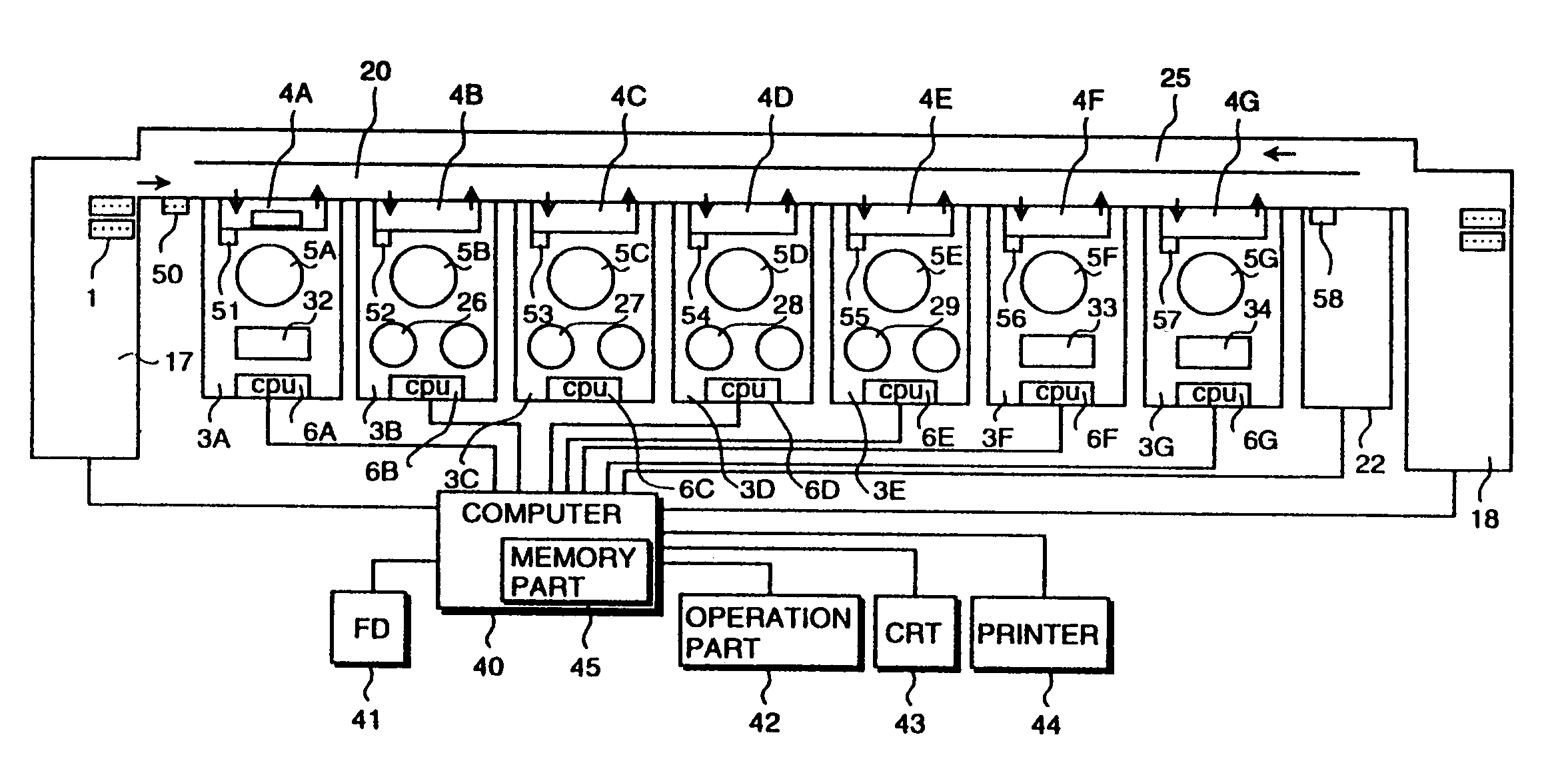
[0007]An object of the present invention is to provide a multiple sample analyzer system which enables an efficient analysis operation even for the analysis time which is requested by a large number of samples, and enables an automated analysis operation without interrupting the analysis operation for the analysis item for which the reagent fluid is short while the analyzer unit is operated.
Problems solved by technology
Therefore, a sample having an analysis item requested by a large number of samples has to wait for completion of analyzing the preceding samples for a longer time than the samples with another analysis item requested by a small number of samples, and consequently, it takes a long time for those samples to obtain the analysis data.
Method used
Image
Click on the blue label to locate the original text in one second.
Reading with bidirectional positioning of images and text.
Examples
Embodiment Construction
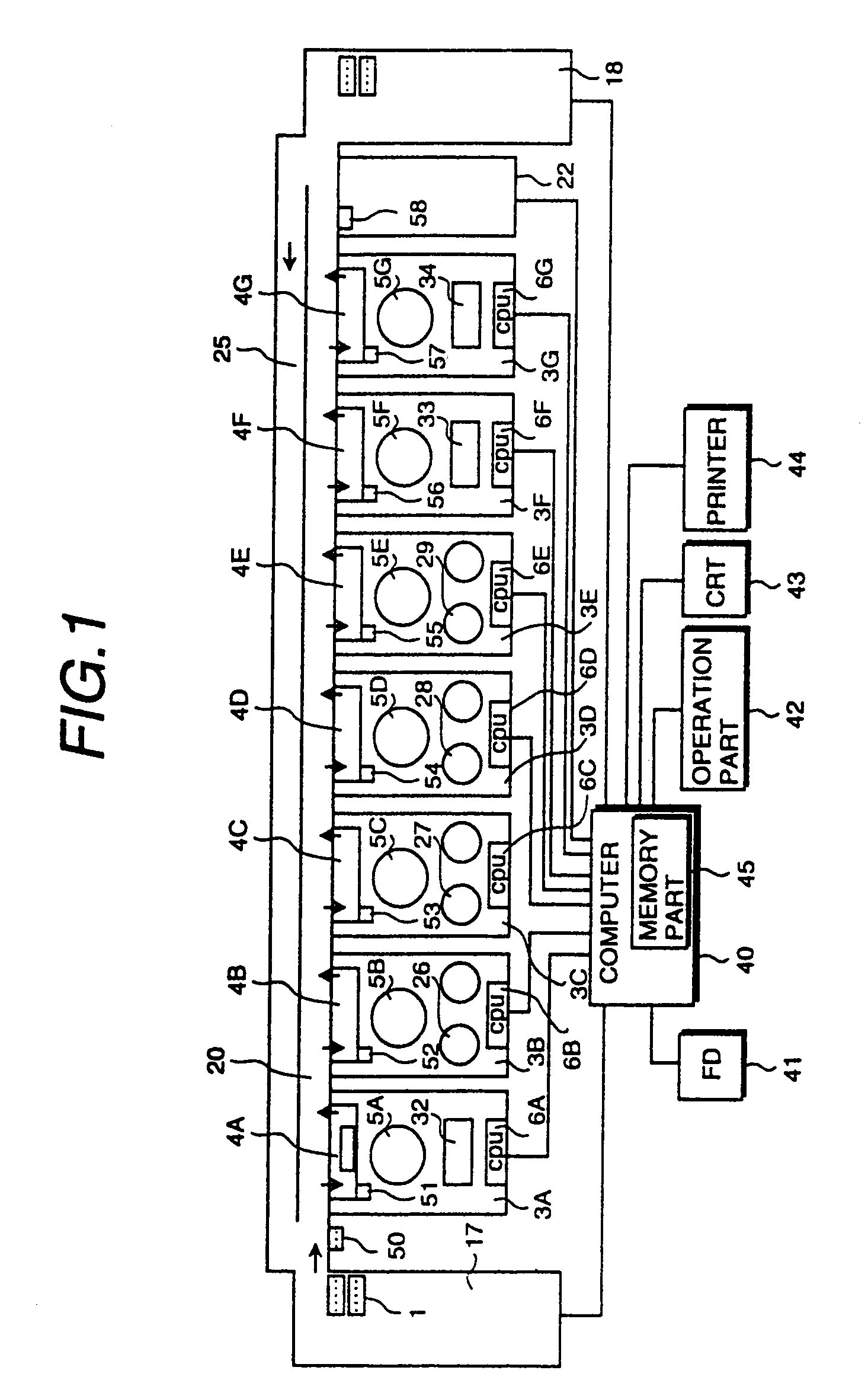
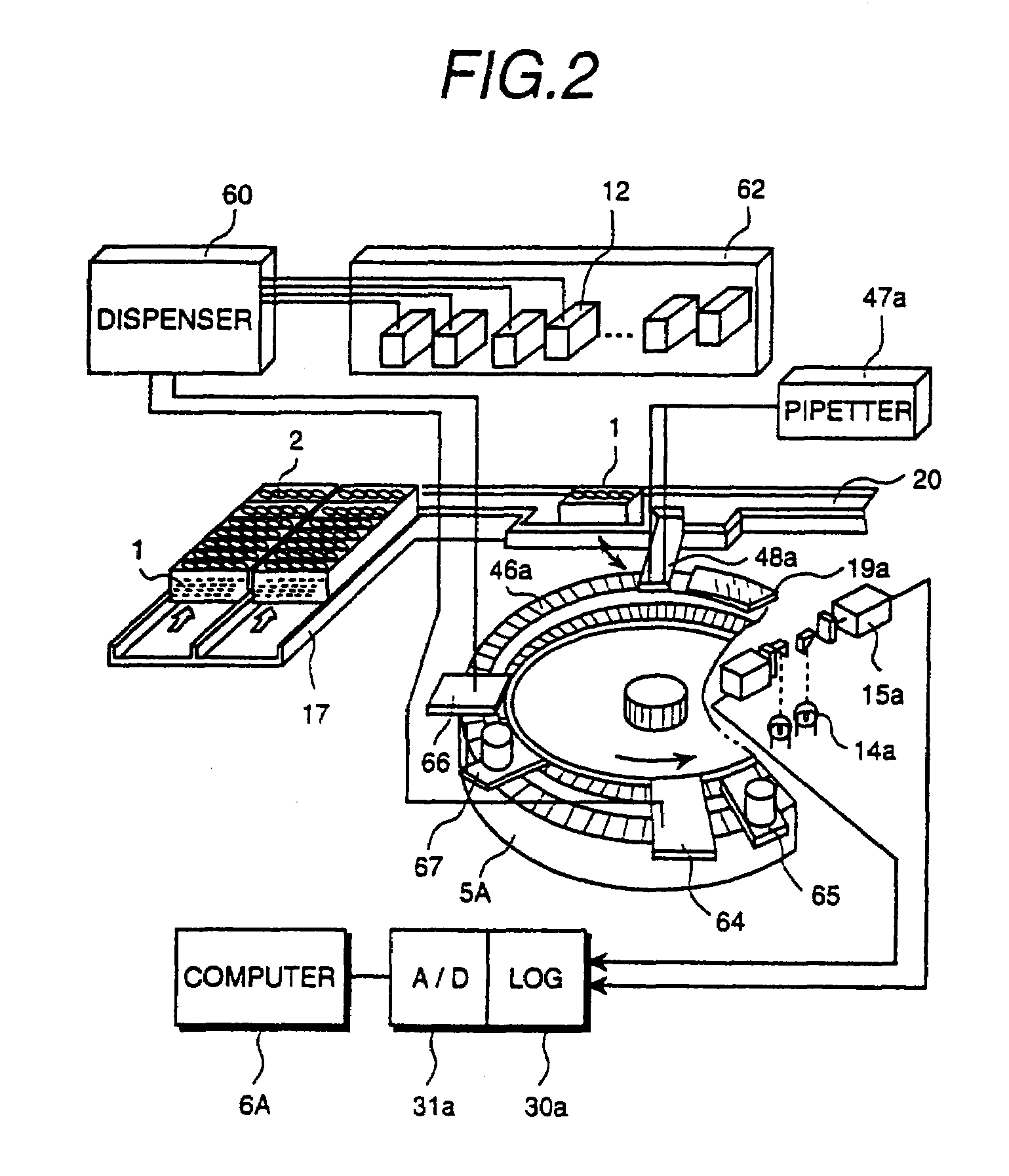
[0016]Preferred embodiments of the present invention will be described below, referring to FIG. 1 to FIG. 4. FIG. 1 shows a schematic construction of the multi-sample analyzer system enabling to analyze samples such as blood serum, blood plasma and urine. In the analyzer system shown in FIG. 1, an analyzer unit supplying samples in a dispenser method as shown in FIG. 2 and an analyzer unit supplying samples in a pipette method are involved. The analyzer units 3A, 3F and 3G in FIG. 1 are dispenser-method based analyzer units, each having fixed analysis channels in which a plurality of sample injection nozzles are assigned to specific samples individually. The analyzer units 3B, 3C, 3D and 3E having an analysis channel not fixed but accessed randomly are pipette-method based analyzer units in which a single reagent pipetting nozzle supplies a designated reagent corresponding to the individual analysis items in a controlled sequence.
[0017]In the analyzer units 3A, 3B and 3C shown in FI...
PUM
Property
Measurement
Unit
temperature
aaaaa
aaaaa
time
aaaaa
aaaaa
area
aaaaa
aaaaa
Abstract
A plurality of analyzer units for serum, a plurality of analyzer units for blood plasma and a plurality of analyzer units for urine are arranged along a main transfer line for transferring a sample rack from a rack providing portion to a rack storage portion. A reagent bottle for inspecting liver function is contained in each reagent delivery mechanism of two analyzer units among the plurality of analyzer units for serum. When the reagent for inspecting liver function in one of the two analyzer units is to be short, analysis for the liver function analysis item to samples can be continued by transferring a sample rack from the rack providing portion to the other analyzer unit.
Description
[0001]This is a continuation application of U.S. application Ser. No. 11 / 324,299, filed Jan. 4, 2006, now U.S. Pat. No. 7,361,305, which is a continuation application of U.S. application Ser. No. 10 / 752,692, filed Jan. 8, 2004, now U.S. Pat. No. 7,011,792, which is a continuation application of U.S. application Ser. No. 09 / 220,371, filed Dec. 24, 1998, now U.S. Pat. No. 6,733,728, which is a continuation application of U.S. Ser. No. 08 / 813,872, filed Mar. 7, 1997, now U.S. Pat. No. 5,902,549.BACKGROUND OF THE INVENTION[0002]The present invention relates to an analyzer system, and particularly to an analyzer system suitable for transferring a sample rack to a plurality of analyzer units through a transfer line, and analyzing and processing designated analysis items for a plurality of samples.[0003]A multiple-sample analyzer system is known, in which a sample rack containing body fluid samples such as blood and urine is transferred to a plurality of analyzer units through a transfer l...
Claims
Application Information
Patent Timeline
Application Date:The date an application was filed.
Publication Date:The date a patent or application was officially published.
First Publication Date:The earliest publication date of a patent with the same application number.
Issue Date:Publication date of the patent grant document.
PCT Entry Date:The Entry date of PCT National Phase.
Estimated Expiry Date:The statutory expiry date of a patent right according to the Patent Law, and it is the longest term of protection that the patent right can achieve without the termination of the patent right due to other reasons(Term extension factor has been taken into account ).
Invalid Date:Actual expiry date is based on effective date or publication date of legal transaction data of invalid patent.

