
Manufacturing method of pixel structure

a manufacturing method and pixel technology, applied in the direction of electrical equipment, semiconductor devices, instruments, etc., can solve the problems of obvious rc delay effect and display quality degradation, and achieve the effect of reducing the resistance value increasing the length of reducing the distance between scan lines and data lines

Active Publication Date: 2010-04-20
AU OPTRONICS CORP
View PDF12 Cites 2 Cited by
  • Summary
  • Abstract
  • Description
  • Claims
  • Application Information

AI Technical Summary

Benefits of technology

The method effectively reduces the resistance of data and scan lines, addressing issues of flickering and nonuniform brightness, enhancing display quality and process tolerance, and allowing real-time detection of electrical connection issues in large-size display panels.

Problems solved by technology

Furthermore, the increase of resolution of display panels incurs an increase in parasitic capacitance of the lines, thus resulting in an obvious RC delay effect.
In other words, the charging time of the pixel structure close to a signal input end is apparently different from that of the pixel structure away from the signal input end, and thus problems of flickering of display, nonuniform brightness, or different charging rates occur, and the display quality is degraded.

Method used


Image

  • Manufacturing method of pixel structure
  • Manufacturing method of pixel structure
  • Manufacturing method of pixel structure

Examples


first embodiment

The First Embodiment

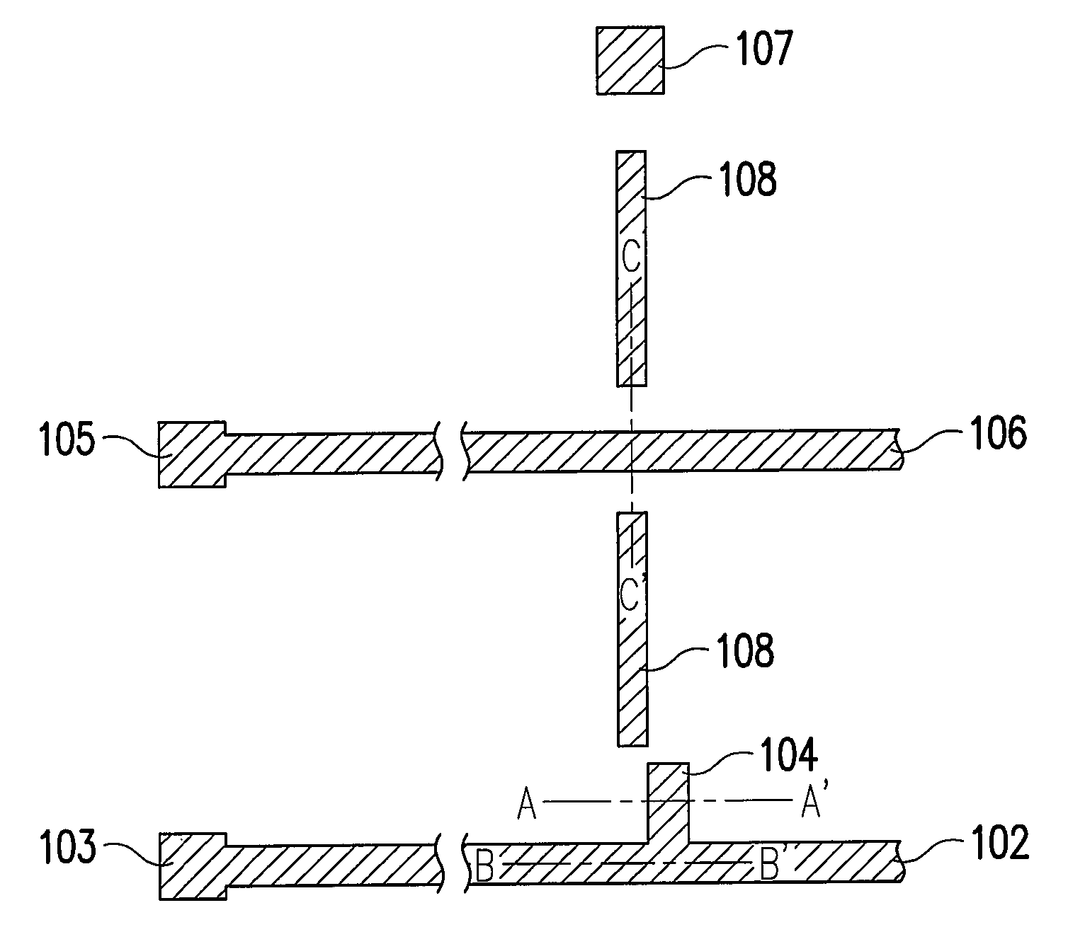
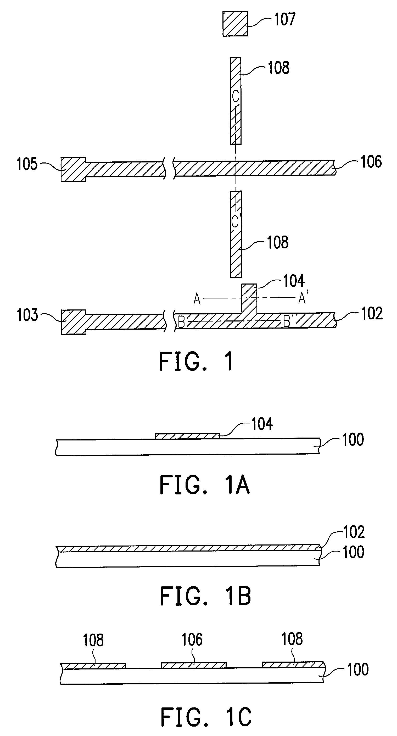
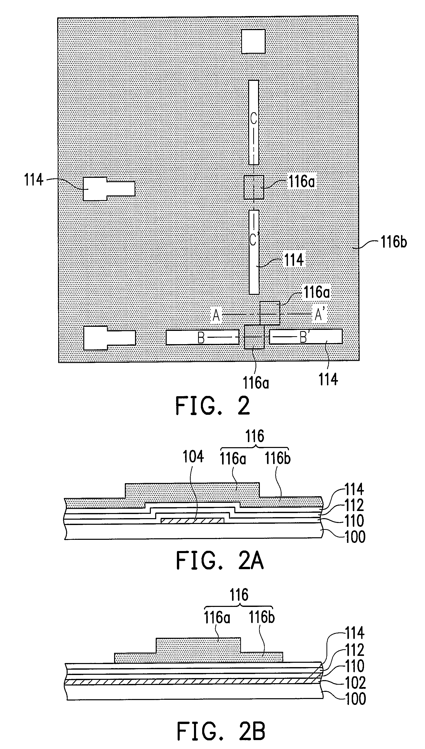
[0024]FIGS. 1-7 are top views of the method of manufacturing the pixel structure according to a preferred embodiment of the present invention, wherein FIGS. 1A, 2A, 3A, 4A, 5A, 6A, and 7A are cross-sectional views along Line A-A′ in the top views, respectively; FIGS. 1B, 2B, 3B, 4B, 5B, 6B, and 7B are cross-sectional views along Line B-B′ in the top views, respectively; and FIGS. 1C, 2C, 3C, 4C, 5C, 6C, and 7C are cross-sectional views along Line C-C′ in the top views, respectively. First, referring to FIGS. 1, 1A, 1B, and 1C, a scan line 102, a gate 104 connected to the scan line 102, and at least one first auxiliary pattern 108 are formed on a substrate 100. In a preferred embodiment, the aforementioned step further comprises forming a bottom electrode line 106 on the substrate 100. In another preferred embodiment, the aforementioned step further comprises forming a scan line terminal 103 connected to the scan line 102 on the substrate 100. Additionally, a bott...

second embodiment

The Second Embodiment

[0033]FIGS. 9-14 are top views of the method of manufacturing the pixel structure according to another preferred embodiment of the present invention, wherein FIGS. 9A, 10A, 11A, 12A, 13A, and 14A are cross-sectional views along Line A-A′ in the top views; FIGS. 9B, 10B, 11B, 12B, 13B, and 14B are cross-sectional views along Line B-B′; and FIGS. 9C, 10C, 11C, 12C, 13C, and 14C are cross-sectional views along Line C-C′. First, referring to FIGS. 9, 9A, 9B, and 9C, a scan line 102, a gate 104 connected to the scan line 102, and at least one first auxiliary pattern 108 are formed on a substrate 100. In a preferred embodiment, the aforementioned step further comprises forming a bottom electrode line 106 on the substrate 100. In another preferred embodiment, the aforementioned step further comprises forming a scan line terminal 103 connected to the scan line 102 on the substrate 100. Additionally, a bottom electrode terminal 105 connected to the bottom electrode line ...


PUM


Abstract

A method of manufacturing a pixel structure is provided. A gate, a scan line, and at least one first auxiliary pattern are formed on a substrate. A gate insulating layer is formed on the substrate to cover the gate and the scan line and expose the first auxiliary pattern and a part of the scan line. A channel layer is formed on the gate insulating layer over the gate. A source, a drain, a data line, a top electrode, and at least one second auxiliary pattern are formed, wherein the data line is electrically connected to the exposed first auxiliary pattern and the second auxiliary pattern is electrically connected to the exposed scan line. A passivation layer and a pixel electrode are formed, and the pixel electrode is electrically connected to the drain and the top electrode.

Description

CROSS-REFERENCE TO RELATED APPLICATION[0001]This application claims the priority benefit of Taiwan application serial no. 95113330, filed Apr. 14, 2006. All disclosure of the Taiwan application is incorporated herein by reference.BACKGROUND OF THE INVENTION[0002]1. Field of the Invention[0003]The present invention relates to a manufacturing method of a pixel structure. More particularly, the present invention relates to a manufacturing method of a pixel structure suitable for a large-size display panel.[0004]2. Description of Related Art[0005]In modern society, well-developed multimedia technology has mostly benefited from the advance of semiconductor devices or display devices. As for displays, thin film transistor liquid crystal displays (TFT-LCDs) with the advantages of high picture quality, preferable space utilization efficiency, low power consumption, and no radiation have become a mainstream product in the market, such that TFTs have been widely used in the TFT-LCDs.[0006]Gen...

Claims


Application Information

Patent Timeline
Patent Type & Authority Patents(United States)
IPC IPC(8): H01L21/00
CPCH01L27/1288H01L27/124G02F1/1362
Inventor TUNG, CHUN-HAO
Owner AU OPTRONICS CORP
Learn More