Color processing apparatus and method

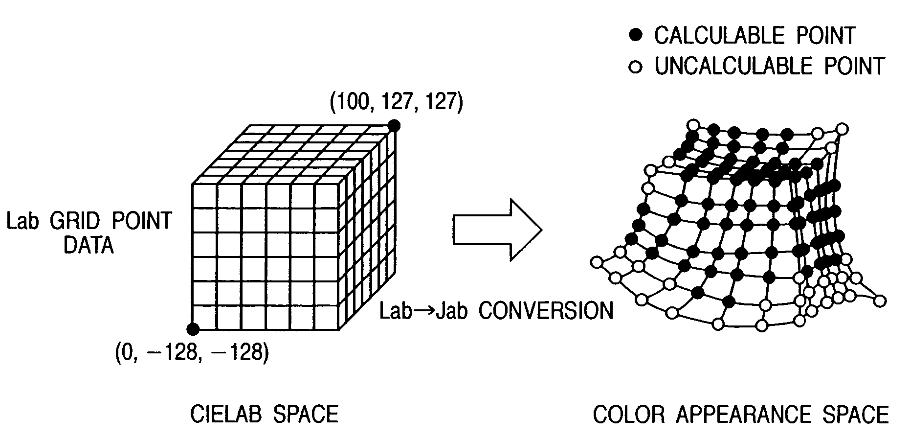
a processing apparatus and color technology, applied in the field of color processing apparatus and method, can solve the problems of inability to input images, disable calculations, and color values j*a*b* of the color appearance space that do not support colors outside of the visible region

Inactive Publication Date: 2010-04-20
CANON KK
View PDF30 Cites 16 Cited by
  • Summary
  • Abstract
  • Description
  • Claims
  • Application Information

AI Technical Summary

Problems solved by technology

However, the conversion formula required to obtain the color values J*a*b* of the color appearance space does not support colors outside of the visible region.
However, (cA / d) often assumes a negative value when a color outside of the visible region is input, and this disables the calculations.
In practice, when color matching is done by the processing system of the ICC profile, it is impossible for an input image to include a color outside of the visible region, but a color in proximity to a boundary of the visible region often exists in an input image.
However, the method disclosed in this reference is different from the method described in FIG. 2.
However, since this technique requires a special apparatus for color matching, it cannot be used in a general image manipulation application such as PhotoShop®.
Not only when an ICC profile is generated but also when a process is made on the color appearance space, it is inconvenient that colors outside of the visible region are not supported.

Method used


Image

  • Color processing apparatus and method
  • Color processing apparatus and method
  • Color processing apparatus and method

Examples


first embodiment

[0048]A process for generating an ICC profile (or a lookup table complying with the ICC compatible profile format) as the first embodiment of the present invention will be described in detail hereinafter with reference the accompanying drawings.

[Arrangement]

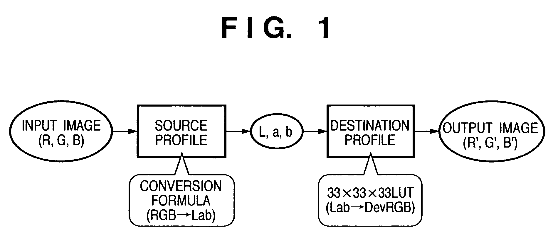
[0049]FIG. 4 is a block diagram showing the arrangement an image processing apparatus 1 according to the first embodiment.

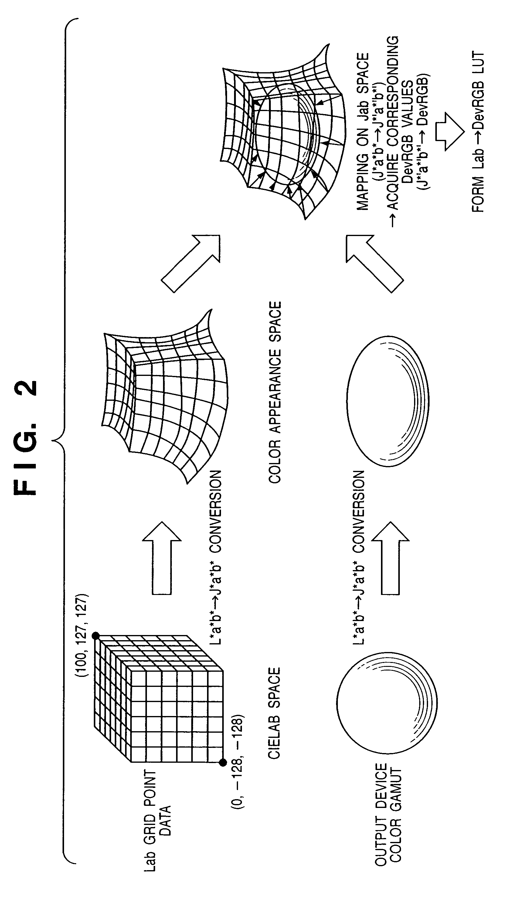
[0050]The image processing apparatus 1 has an input section 101 for inputting color gamut data of an output device, an XYZ calculator 102 for calculating CIEXYZ tristimulus values from grid point information (L*a*b*) on the CIELAB space stored in an LUT memory 108, and a color appearance converter 103 for calculating J*a*b* values using color appearance conversion formulas from the XYZ values calculated by the XYZ calculator 102, an output section 104 for outputting an LUT. Also provided is a nearest neighboring point calculator 105 for retrieving a point which can be converted into J*a*b* values and becomes a...

second embodiment

[0079]An image process according to the second embodiment of the present invention will be described below. Note that the same reference numerals in the second embodiment denote the same parts as in the first embodiment, and a detailed description thereof will be omitted.

[0080]FIG. 17 is a block diagram showing the arrangement of an image processing apparatus 1 according to the second embodiment. The difference from the arrangement of the first embodiment shown in FIG. 4 is as follows. In the first embodiment, for a point which cannot be converted into J*a*b* values by the color appearance converter 103, the nearest neighboring point calculator 105 retrieves a point that can be converted and uses that point as a nearest neighboring point, to calculate J*a*b* values for the point that cannot be converted. In place of this nearest neighboring point calculator 105, the second embodiment has a grid point prediction section 115 which predicts the J*a*b* values of the point that cannot be...

third embodiment

[0097]An image process according to the third embodiment of the present invention will be described below. Note that the same reference numerals in the third embodiment denote substantially the same parts as in the first and second embodiments, and a detailed description thereof will be omitted.

[0098]FIG. 22 is a block diagram showing the arrangement of an image processing apparatus 1 according to the third embodiment. The difference from the arrangement of the first embodiment shown in FIG. 4 is as follows. In the first embodiment, for a point that cannot be converted into J*a*b* values by the color appearance converter 103, the nearest neighboring point calculator 105 retrieves a point that can be converted and uses that point as a nearest neighboring point, to calculate J*a*b* values for the point that cannot be converted. In place of this nearest neighboring point calculator 105, the third embodiment has a weighting calculator 125, which calculates DevRGB values of a mapping des...


PUM

PropertyMeasurementUnit
coloraaaaaaaaaa
color appearanceaaaaaaaaaa
color appearance conversionaaaaaaaaaa

Abstract

It is desired to adopt gamut mapping using a color appearance space in the processing system of an ICC profile. Upon generating an LUT complying with the ICC profile format, when CIEL*a*b* values are converted into CIEXYZ values, and the XYZ values are converted into color appearance space values using color appearance conversion formulas, a point which can be converted and becomes a nearest neighboring point for a point that satisfies a predetermined condition is retrieved, and corresponding color appearance space values are calculated. The obtained color appearance space values are mapped on a predetermined device gamut.

Description

FIELD OF THE INVENTION[0001]The present invention relates to a color processing apparatus and method and, more particularly, to a color process for generating a lookup table.BACKGROUND OF THE INVENTION[0002]In recent years, along with the popularization of personal computers, it has become easy to input an image using an image input device such as a digital camera, color scanner, or the like, to display and confirm that image using an image display device such as a CRT, LCD, or the like, and to output the image via an image output device such as a color printer or the like. In this case, in order to correct any color appearance difference due to the difference between color gamuts of the display and output devices, a color matching process (gamut mapping) is normally executed. That is, the color appearance difference between the devices is compensated for by the color matching process.[0003]One such color matching process is a method using an ICC profile. Note that the ICC profile i...

Claims


Application Information

Patent Timeline
Patent Type & Authority Patents(United States)
IPC IPC(8): G09G5/02G06T1/00G03F3/08G06F15/00G09G5/06H04N1/46H04N1/60
CPCH04N1/6058
Inventor SUZUKI, TAKAHIROYAMADA, OSAMU
Owner CANON KK
Why Eureka
Try Eureka