
Video magnifer with irradiating pointer

a technology of video magnifiers and pointers, which is applied in the field of video magnifiers, can solve the problems of difficult confinement of the location of the object irradiated by the pointer, the difficulty of weak-sighted persons to confirm the location of the object, and the tendency of illumination to dazzle the eyes of weak-sighted people, so as to improve the convenience of video magnifiers, and facilitate transfer and installation

Inactive Publication Date: 2010-04-20
ELMO CO LTD +1
View PDF13 Cites 19 Cited by
  • Summary
  • Abstract
  • Description
  • Claims
  • Application Information

AI Technical Summary

Benefits of technology

[0007]Therefore, an object of the present invention is to provide a video magnifier in which the weak-sighted persons can readily confirm the location irradiated by the pointer even when both irradiation by the pointer and illumination by the illumination lamp are carried out simultaneously.
[0009]In the above-described video magnifier, the illuminance of the illumination lamp is rendered lower than that of the pointer in synchronization with irradiation of the photographing location by the pointer. Accordingly, since irradiation of the photographing location by the pointer is confirmed readily, the photographing location of the video camera can easily correspond with a part of the document to be read. Consequently, the convenience of the video magnifier can be improved.
[0011]In another preferred form, the table is movable back and forth, and right and left. Consequently, the location irradiated by the pointer can easily be caused to correspond with the part of the document to be read, whereupon the convenience of the video magnifier can be improved.
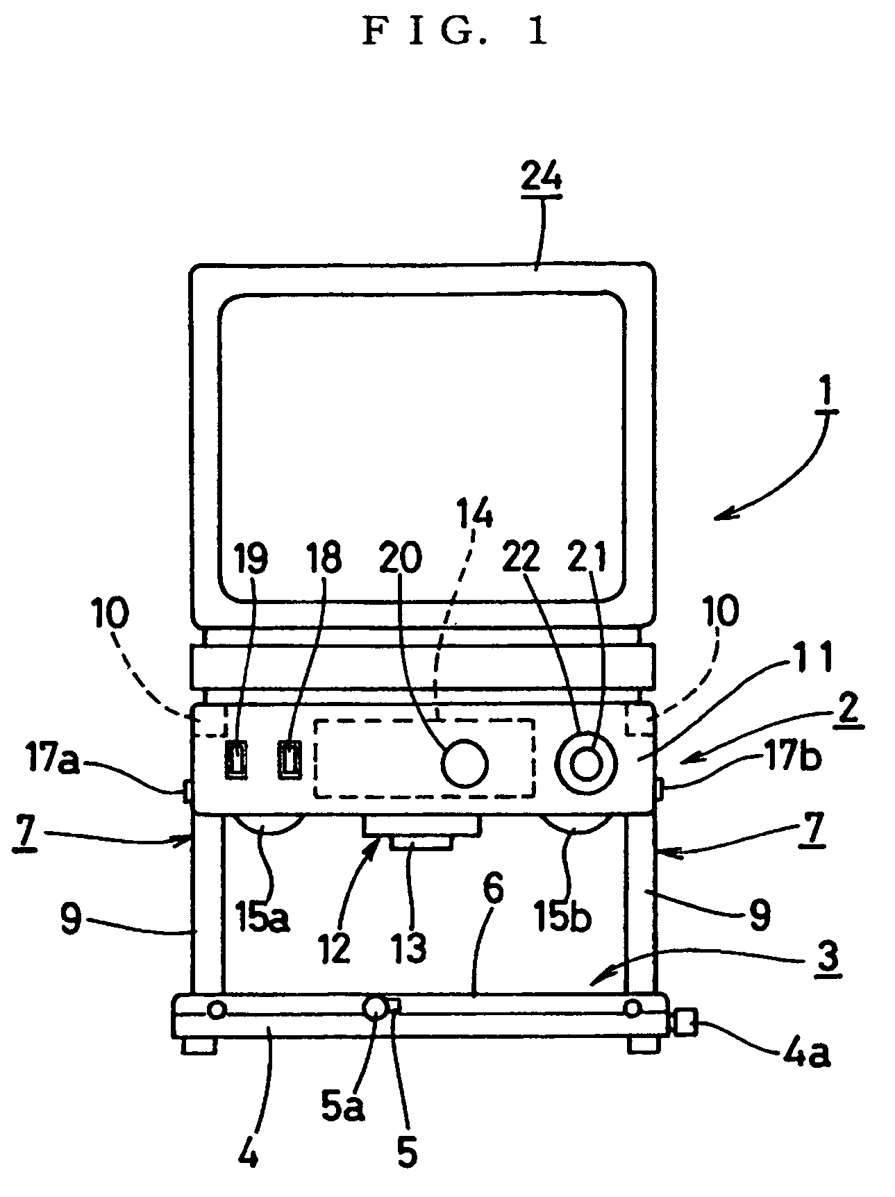
[0013]In further another preferred form, a support arm is provided on the base, and the video camera, the illumination lamp or lamps and the pointer are housed in a casing. The casing is disposed over the table by the support arm, and the monitor television is disposed on an upper side of the casing. Consequently, the convenience of the video magnifier can be improved since movement of a look decreases between the irradiation position of the pointer and the screen of the monitor television. Further, the video magnifier can easily be transferred and installed since the monitor television detachably placed on the upper side of the casing.

Problems solved by technology

However, the illumination by the illumination lamp tends to dazzle eyes of the weak-sighted persons.
Accordingly, when both irradiation by the pointer and illumination by the illumination lamp are carried out simultaneously, the weak-sighted persons have a difficulty to confirm the location on the object irradiated by the pointer.
As a result, when the video magnifier is used so that an object is read or an entry is made into the object, it is difficult to confine the location to be read within a photographing range.
Thus, the conventional video magnifier has a low convenience.
Further, since most weak-sighted persons also have defective color vision, it is unsuitable to require determination by a color for confirmation of the irradiation location of the pointer.

Method used


Image

  • Video magnifer with irradiating pointer
  • Video magnifer with irradiating pointer
  • Video magnifer with irradiating pointer

Examples


Embodiment Construction

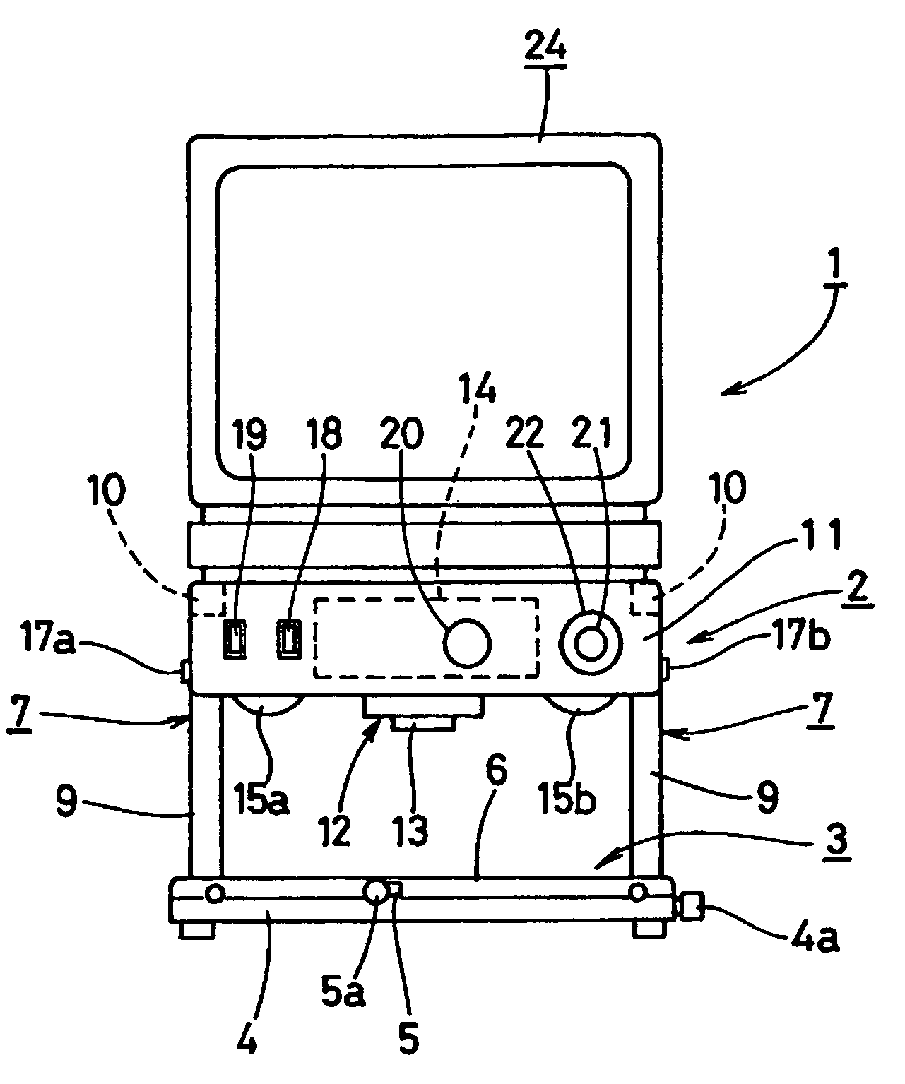
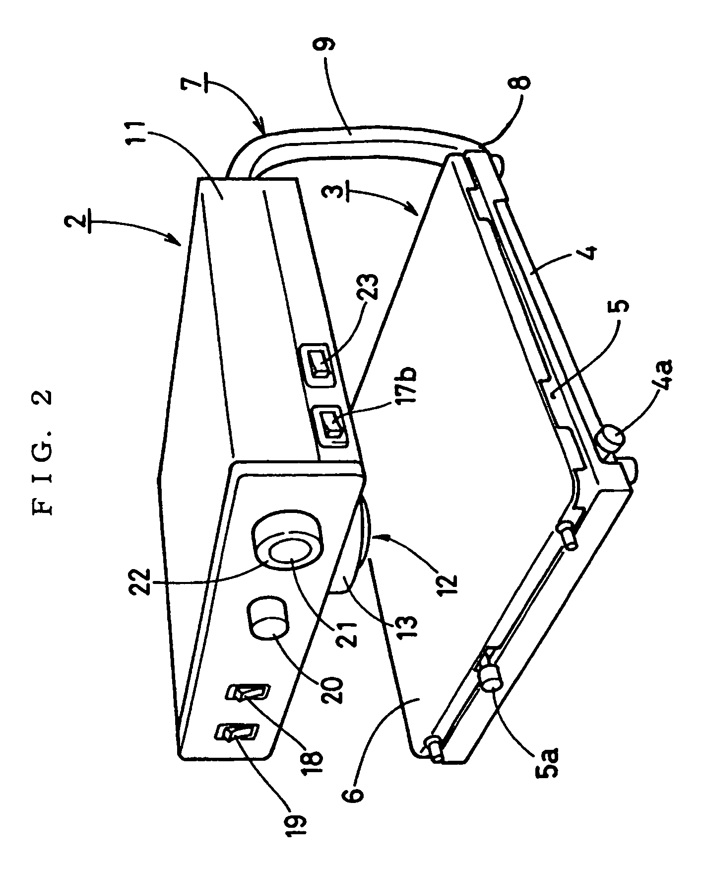
[0020]One embodiment of the present invention will be described with reference to the drawings. Referring to the drawings, the video magnifier 1 of the embodiment includes a body 2 on which a table unit 3 is mounted. An object to be read is placed on the table unit 3. The table unit 3 includes an attachment plate 5 attached to a base 4 and a table 6 mounted on the attachment plate 5. The attachment plate 5 is moved back and forth by a cross slide (not shown) fixed to the base 4. The table 6 is further moved right and left by another cross slide (not shown) fixed to the attachment plate 5. A brake knob 4a is mounted on the base 4 for preventing back-and-forth movement of the attachment plate 5. Another brake knob 5a is mounted on the attachment plate 5 for preventing right-and-left movement of the table 6. Accordingly, when an installation surface for the video magnifier 1 is inclined or when the video magnifier body 2 is shipped or otherwise conveyed, the attachment plate 5, table 6...


PUM


Abstract

A video magnifier includes a body including a base, a table on which an object to be read is placed, the table being disposed on the base, a video camera disposed over the table, an illumination lamp illuminating the object placed on the table and a pointer irradiating a part of the object photographed by the video camera, and a monitor television displaying a video image delivered from the video camera. In the video magnifier, in synchronization with irradiation of the photographed part of the object by the pointer, an illuminance of the illumination lamp is rendered lower than an illuminance of the pointer.

Description

BACKGROUND OF THE INVENTION[0001]1. Field of the Invention[0002]This invention relates to a video magnifier provided with an irradiating pointer which irradiates a part of an object placed on a table with light thereby to point a location corresponding to a magnified image on a monitor screen.[0003]2. Description of the Related Art[0004]One type of video magnifier has been provided with an irradiating pointer which irradiates a part of an object placed on a table with light thereby to point a location corresponding to a magnified image on a monitor screen. JP-A-2000-333042 discloses such a video magnifier with a pointer. Video magnifiers are generally directed to use by weak-sighted persons. An object to be read, such as newspaper, is placed on a table and illuminated by an illumination lamp.[0005]However, the illumination by the illumination lamp tends to dazzle eyes of the weak-sighted persons. Accordingly, when both irradiation by the pointer and illumination by the illumination ...

Claims


Application Information

Patent Timeline
Patent Type & Authority Patents(United States)
IPC IPC(8): H04N7/12H04N5/238H04N5/222H04N5/64H04N7/18
CPCG03B15/03G03B27/323H04N5/23296H04N5/232H04N5/2256H04N23/56H04N23/60H04N23/69
Inventor MIZUKAMI, KATSUYAYAMAGUCHI, SEIJI
Owner ELMO CO LTD
Learn More