Method of measuring front and back surfaces of target object

a target object and front and back surface technology, applied in the direction of optical apparatus testing, optical radiation measurement, instruments, etc., can solve the problems of high cost of jig preparation, measurement errors, and failure to achieve desired optical characteristics, so as to achieve high accuracy and minimize the influence of external forces

Active Publication Date: 2010-04-20
MITUTOYO CORP
View PDF11 Cites 3 Cited by
  • Summary
  • Abstract
  • Description
  • Claims
  • Application Information

AI Technical Summary

Benefits of technology

[0010]An object of the invention is to provide a method of measuring front and back surfaces of a target object highly accurately, efficiently and economically without using reference balls or the like.
[0015]In other words, the measurement position of the second measuring surface corresponding to the measuring position used in the measurement of the first measuring surface of the lens is obtained by comparing the first contour data obtained through the first measurement of the contour with the second contour data obtained through the second measurement of the contour. Thus, without using reference ball or the like, profiles of the front and back surfaces of the target object can be measured. Accordingly, the economic burden incurred from the preparation of the jig can be alleviated, and there is no need to dispose reference balls as well as the target object on a target object-holding jig. Hence, the front and back surfaces of the target object can be highly accurately and efficiently measured. Particularly, since profiles of the front and back surfaces of the lens can be highly accurately measured, displacement and inclination of the optical axis of the lens can be also measured with high accuracy.
[0019]According to the aspect of the invention, in measuring the first measuring surface and the second measuring surface, a scanning measurement for measuring the measuring surface of the target object while bringing the probe into contact with the measuring surface at a constant pressure is conducted. Thus, profiles of the measuring surfaces of the target object can be highly accurately measured.
[0021]According to the aspect of the invention, the vibrator vibrates the stylus, and the vibrating stylus is brought into contact with the front surface of the target object. Since the vibration of the stylus is restrained when the stylus contacts the front surface of the target object, the detection signal from the sensor element is attenuated. Thus, by conducting the measurement while controlling the stylus moving mechanism such that the attenuation amount of the detection signal from the sensor element becomes always constant, a highly accurate measurement can be realized. Particularly, since a vibratory probe is employed, the measurement can be conducted even with a small measuring force, thereby contributing to minimization of influence of external forces on the target object.

Problems solved by technology

Such misalignment may hamper achievement of desired optical characteristics.
However, since the above-described method requires high-precision balls to be used as the reference balls, preparation of the jig tends to incur high cost.
In addition, the coordinates of the centers of the reference balls are calculated by partially measuring the exposed potions of the reference balls, which may lead to measurement errors.

Method used


Image

  • Method of measuring front and back surfaces of target object
  • Method of measuring front and back surfaces of target object
  • Method of measuring front and back surfaces of target object

Examples


Embodiment Construction

)

1 and 2)>

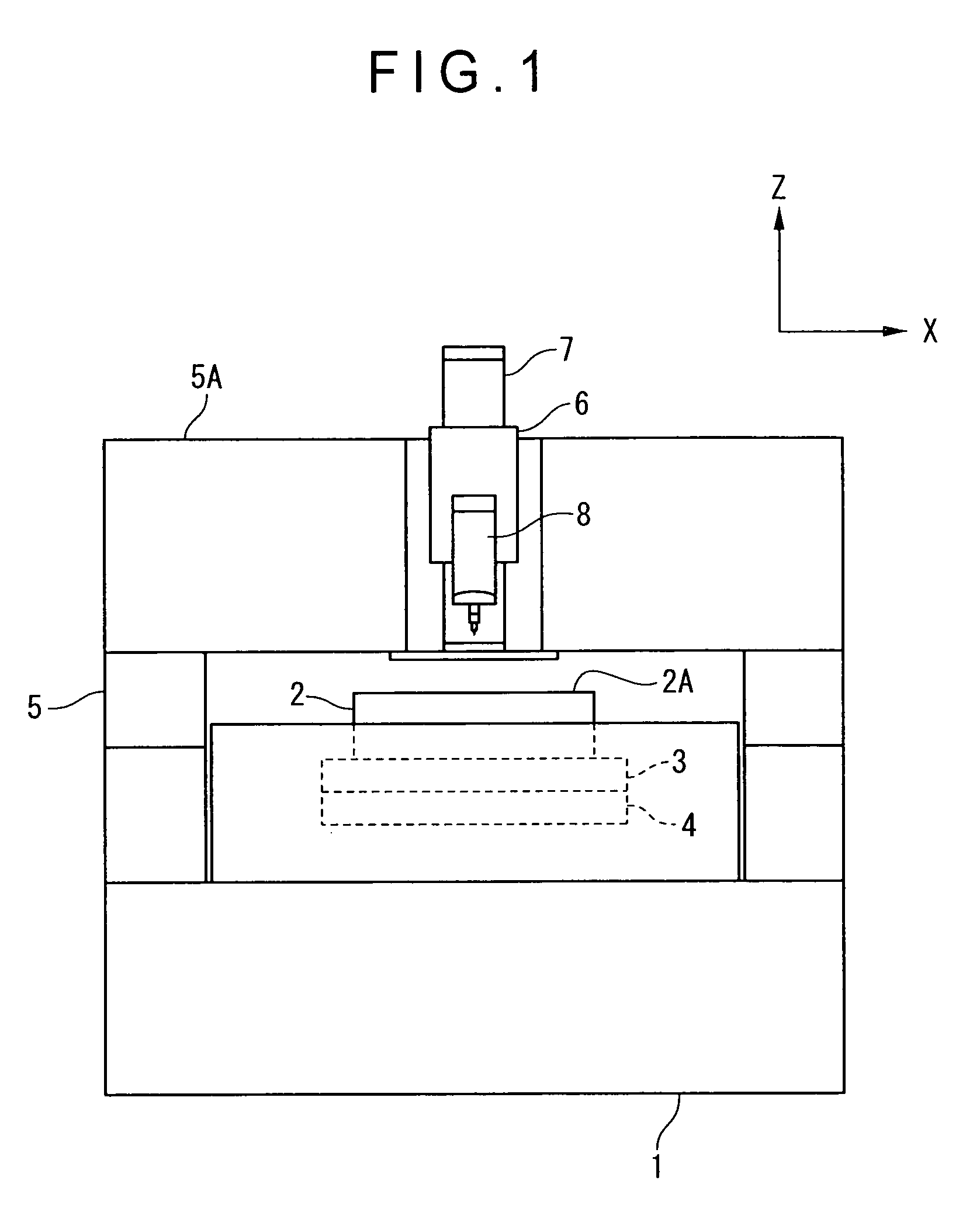
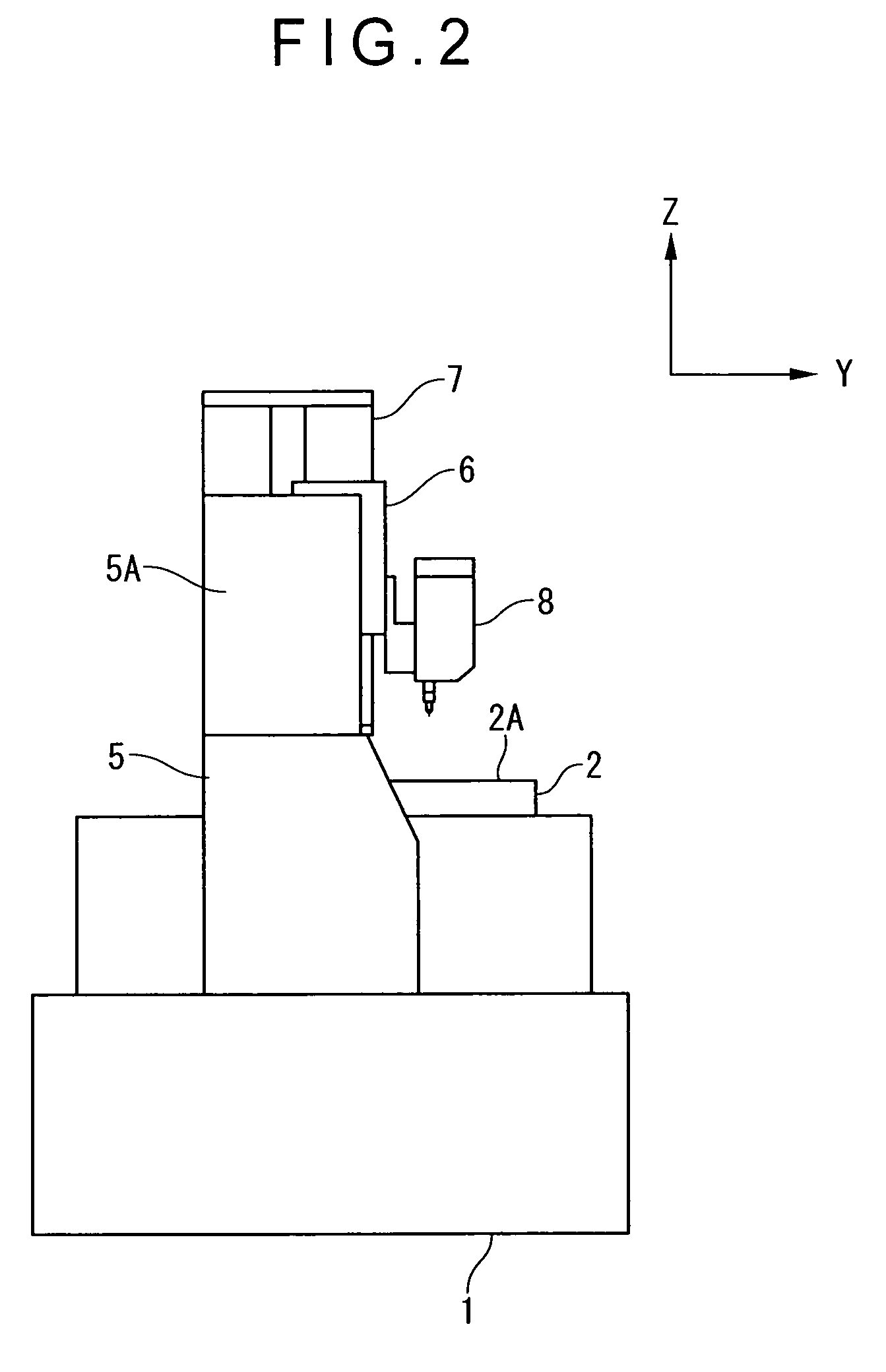
[0037]FIG. 1 is a front view showing a surface texture measuring instrument for conducting a method according to the invention. FIG. 2 is a lateral view showing the surface texture measuring instrument.

[0038]The surface texture measuring instrument includes: a base 1; an XY stage 2 (table) on which a target object is placed; an X-axis driving mechanism 3 and a Y-axis driving mechanism 4 for displacing the XY stage 2 in X-axis and Y-axis directions respectively within a horizontal plane; a portal frame 5 provided over the base 1 in a bridging manner; a Z-axis slider 6 (movable member) provided on a cross rail 5A of the portal frame 5; a Z-axis driving mechanism 7 for displacing the Z-axis slider 6 in a Z-axis direction that is perpendicular to the X-axis and Y-axis directions; and a probe 8 mounted on the Z-axis slider 6.

[0039]The XY stage 2, a top face of which includes a flat stage surface 2A on which a target object is placed, is movable in the X-axis and Y-axis directio...


PUM


Abstract

A method of measuring a front surface profile and a back surface profile of a target object includes: mounting the target object in such a posture that a first measuring surface (front surface) is measurable by a probe; first measuring a contour of the target object; measuring the first measuring surface of the target object; reversing the target object; second measuring the contour of the target object with the reversed posture of the target object being maintained; obtaining a measurement position of a second measuring surface by comparison of contour data obtained through the first and second measuring of the contour, the measurement position of the second measuring surface corresponding to a measurement position of the first measuring surface at which the measuring of the first measuring surface is conducted; and measuring a profile of the second measuring surface along the obtained measurement position of the second measuring surface.

Description

BACKGROUND OF THE INVENTION[0001]1. Field of the Invention[0002]The present invention relates to a method of measuring front and back surfaces of a target object. For instance, the method according to an aspect of the invention relates to a method of measuring a front surface profile and a back surface profile of a lens.[0003]2. Description of Related Art[0004]When lenses are manufactured through transfer using metal molds, the optical axis of front surfaces of the manufactured lenses may be misaligned with the optical axis of back surfaces of the manufactured lenses, depending on precision and displacement of the metal molds. Such misalignment may hamper achievement of desired optical characteristics.[0005]In view of the above, various proposals have been made on methods of measuring profiles of front and back surfaces of lenses.[0006]For instance, a document 1 (JP-A-2006-78398) discloses a method and a device of measuring eccentricity and inclination of front and back surfaces.[00...

Claims


Application Information

Patent Timeline
Patent Type & Authority Patents(United States)
IPC IPC(8): G01B9/00
CPCG01B5/008G01M11/025G01B5/252G01B5/20
Inventor NEMOTO, KENTAROYAMAGATA, MASAOKI
Owner MITUTOYO CORP
Why Eureka
Try Eureka