Apparatus for three phase PWM cycloconverter

a cycloconverter and three-phase technology, applied in the field of power converters, can solve problems such as output voltage error, and achieve the effects of eliminating small pwm pulse width, and reducing output voltage and output current distortion

Active Publication Date: 2010-04-20
YASKAWA DENKI KK
View PDF11 Cites 32 Cited by
  • Summary
  • Abstract
  • Description
  • Claims
  • Application Information

AI Technical Summary

Benefits of technology

[0045]According to the first and second aspects of the invention, there are provided the one-phase fixing switching mode for fixing one of the output phases into a predetermined state without switching and switching the other phases, and the full phase switching mode for switching all of the phases during a PWM cycle. In the case where the PWM pulse width is reduced, therefore, it is possible to eliminate the small PWM pulse width, to reduce distortions of the output voltage and the output current, and to reliably correct a voltage drop in respect of characteristics of a commutating sequence and a semiconductor device.
[0046]According to the third and fourth aspects of the invention, moreover, the switching from the one-phase fixing switching mode to the full phase switching mode is carried out based on a phase of the AC source voltage, a voltage or a phase of a voltage to be output. Therefore, it is possible to eliminate a small PWM pulse width without monitoring the PWM pulse width, to reduce distortions of an output voltage and an output current by a simple control, and to reliably correct a voltage drop in respect of the commutating sequence and the characteristic of the semiconductor device.
[0047]According to the fifth and sixth aspects of the invention, it is possible to eliminate a small PWM pulse width without monitoring the PWM pulse width based on a voltage to be output, to reduce distortions of an output voltage and an output current by a simple control, and to reliably correct a voltage drop in respect of the commutating sequence and the characteristic of the semiconductor device.
[0048]According to the seventh aspect of the invention, there are provided the one-phase fixing switching mode for fixing one of the output phases into a predetermined state without switching and switching the other phases, and the full phase switching mode for switching all of the phases during a PWM cycle. In the case where the PWM pulse width is reduced, therefore, the switch from the one-phase fixing switching mode to the full phase switching mode is carried out. Consequently, it is possible to provide a power conversion method that can eliminate the small PWM pulse width, can reduce distortions of the output voltage and the output current, and can reliably correct a voltage drop in respect of a commutating sequence and a characteristic of a semiconductor device.
[0049]According to the eighth aspect of the invention, the space vector is utilized to carry out a calculation processing. Therefore, it is possible to easily execute a processing of calculating an output voltage.
[0050]According to the ninth aspect of the invention, the distortion of the output voltage is decreased by the PWM control.

Problems solved by technology

When a current flows to the bidirectional switch, furthermore, a voltage drop is caused in respect of a characteristic of a semiconductor device so that an error of the output voltage is made.

Method used


Image

  • Apparatus for three phase PWM cycloconverter
  • Apparatus for three phase PWM cycloconverter
  • Apparatus for three phase PWM cycloconverter

Examples


first example

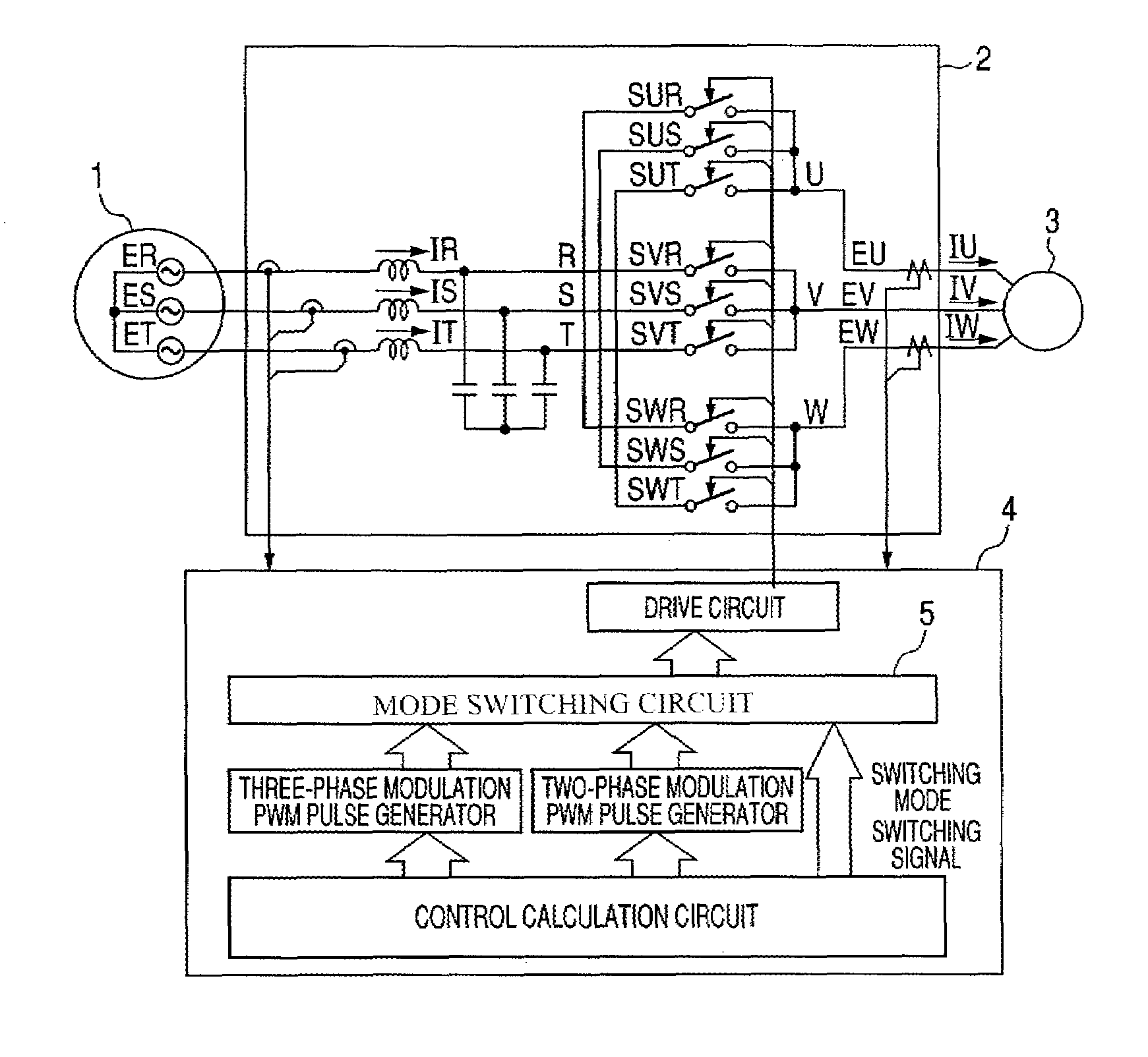
[0079]FIG. 1 is a diagram showing an example of a structure of a power converter according to the present invention. In the drawing, 1 denotes a three-phase power supply, 2 denotes a main circuit of a direct power converter, 3 denotes a load (a motor), and 4 denotes a control circuit of a direct power converting circuit.

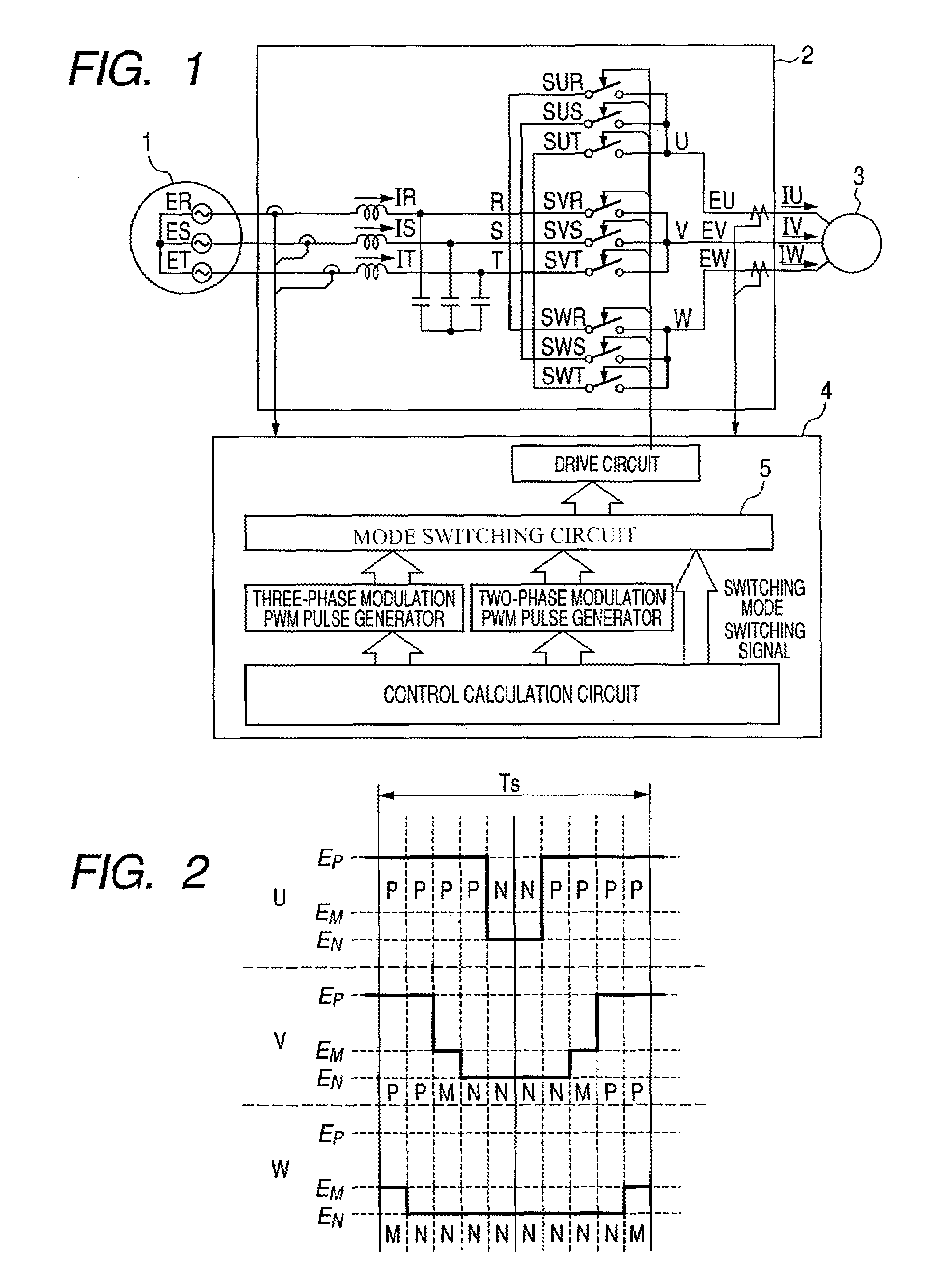
[0080]Referring to a three-phase source voltage and a phase, a maximum voltage phase, a minimum voltage phase and an intermediate voltage phase seen from a neutral point are allocated as P, N and M respectively as shown in FIG. 6, and a concept of a space vector is utilized so that an output voltage space vector of a direct power converting circuit can be written as in an example of FIG. 7. In the power converter, usually, a neutral point voltage cannot be directly observed. Therefore, resistances having a value equal to each other are connected like a star in each of phases of a three-phase power supply as shown in FIG. 12, a node voltage is used as a virtual neutra...

second example

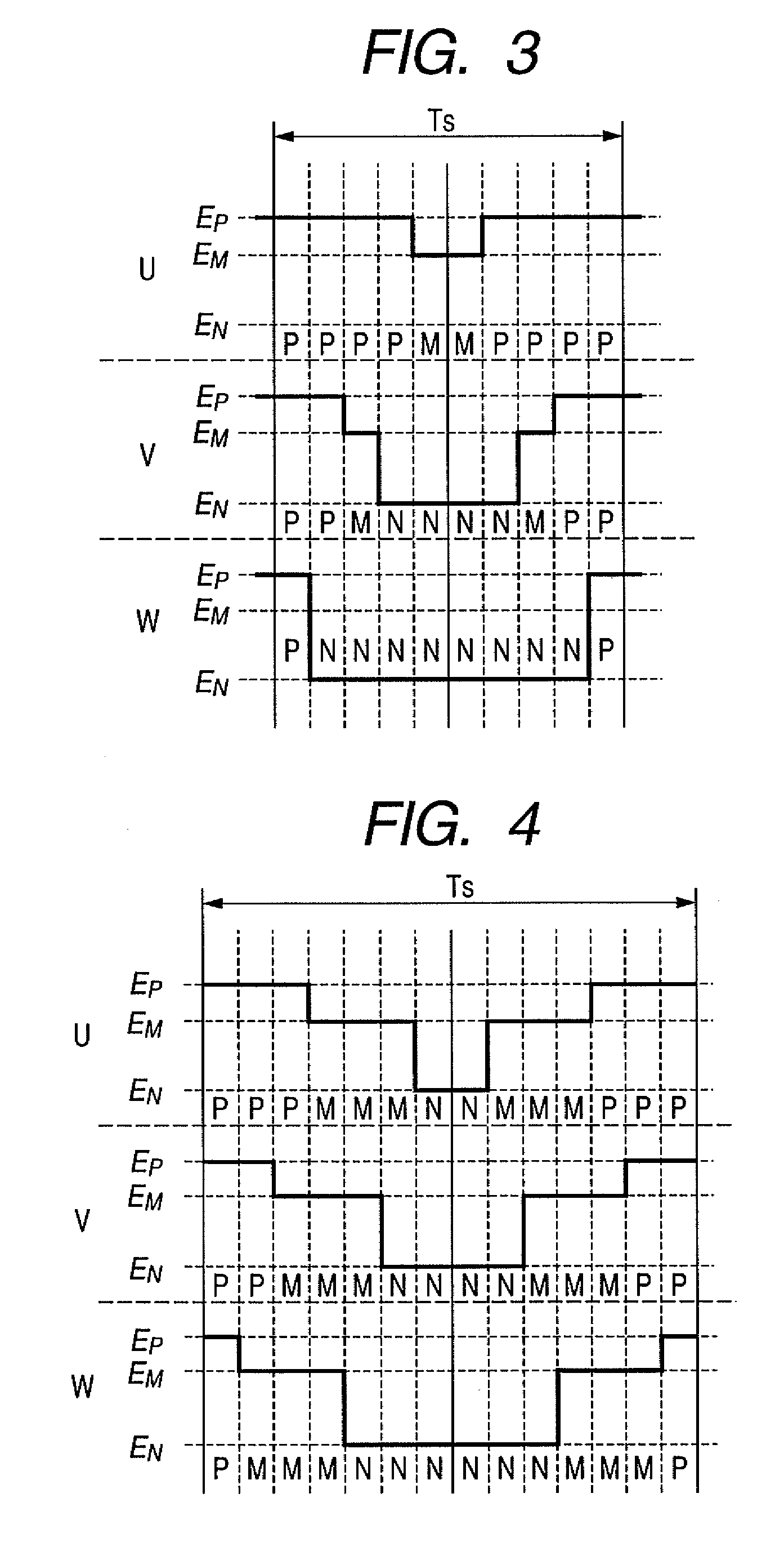
[0085]In the case in which an output voltage command is in the vicinity of an angle formed with an a vector or a b vector, a PWM pulse is narrowed. In a direct power converter, the angles of the a vector and the b vector are not varied. In the case in which the phase of the output voltage command has an angle which is close to the a vector or the b vector, therefore, it is possible to maintain a PWM pulse width without monitoring the PWM pulse width by generating a switching signal to carry out a switching into a three-phase modulation in the control calculating apparatus of FIG. 1. Since a range of the angle to be switched depends on a commutating sequence method and a characteristic of a switching device, it is set corresponding thereto.

third example

[0086]Also in the case in which there is no problem in that a PWM pulse width is reduced when a switching is carried out depending on a phase of an output voltage command, the switch is performed so that a switching loss is increased. A change in the PWM pulse of FIG. 9 and the PWM pulse of FIG. 10 depends on a voltage state of an input power supply. Therefore, a condition for reducing the PWM pulse width is predicted from the voltage of the input power supply and the phase of the output voltage command. For example, only in the case in which the phase of the output voltage command is close to the angle of the b vector in FIG. 9, it is possible to reduce the switching loss by carrying out a switching from a two-phase modulation into a three-phase modulation. Since the range of the angle to be switched depends on a commutating sequence method and a characteristic of a switching device, it is set corresponding thereto.


PUM


Abstract

A power conversion method comprising detecting a three-phase source voltage of the three-phase AC power supply every control sampling cycle. The three-phase source voltage is allocated to a maximum voltage, an intermediate voltage and a minimum voltage as seen from a virtual neutral point voltage. A one-phase fixing switching mode is detected for fixing one of output phases into a predetermined state without switching and switching the other phases during a PWM cycle or a full phase switching mode for switching all of the phases during the PWM cycle based on an output voltage command and the three-phase source voltage. ON / OFF pattern of a bidirectional switch is determined from the switching mode thus selected, the output voltage command and the three-phase source voltage. The bidirectional switch is turned ON / OFF based on the ON / OFF pattern.

Description

TECHNICAL FIELD[0001]The present invention relates to a power converter capable of carrying out a power conversion into an optional frequency from an AC power supply, and more particularly to a power converter and a power conversion method which use a pulse width modulation (PWM) control and a direct torque control.BACKGROUND ART[0002]A matrix converter can connect each phase of an AC power supply to output phase through a circuit structure of a bidirectional switch having a self-extinction capability and can directly convert an AC power into any voltage and frequency. In order to forcibly switch a current flowing to the switch, however, it is necessary to provide a unique switching sequence. The switching sequence will be hereinafter referred to as a commutating sequence. A switching sequence of a PWM cycloconverter has been disclosed in Patent Document 1 and Patent Document 2.[0003]Examples of a method of creating a commutating sequence include a method of creating a commutating s...

Claims


Application Information

Patent Timeline
Patent Type & Authority Patents(United States)
IPC IPC(8): H02M5/00
CPCH02M5/297H02M5/293
Inventor YAMANAKA, KATSUTOSHI
Owner YASKAWA DENKI KK
Why Eureka
Try Eureka