
Method for transmitting communication data in a communication system

a communication system and communication data technology, applied in data switching networks, digital transmission, network connections, etc., can solve the problems of loss in the quality of user data to be transmitted between two communication, etc., to reduce the loss of quality during the transmission of user data between heterogeneous transmission methods

Active Publication Date: 2010-04-20
UNIFY GMBH & CO KG
View PDF17 Cites 6 Cited by
  • Summary
  • Abstract
  • Description
  • Claims
  • Application Information

AI Technical Summary

Benefits of technology

The invention provides a method for reducing quality loss during the transmission of user data between different communication methods and networks. The method involves setting up a primary connection between two communication units and using an ingress or egress node for a secondary connection. The primary connection is set up based on the addressing data of the communication units and the network, and the secondary connection is set up based on the addressing data of the ingress or egress node. The method ensures that data is transmitted directly between the ingress and egress nodes, avoiding multiple conversions and resulting in improved quality of the transmitted data. The method can be applied to heterogeneous communication systems, improving the quality of the transmitted data.

Problems solved by technology

As a result of the use of packet-oriented data transmission methods for communication systems of this type there are frequently losses in the quality of the user data to be transmitted, which losses are due primarily to an alternating conversion between a continuous user data stream and user data packets.
Said multiple conversions result in a loss in quality of the user data to be transmitted between the two communication terminals taking part in the connection.

Method used


Image

  • Method for transmitting communication data in a communication system
  • Method for transmitting communication data in a communication system
  • Method for transmitting communication data in a communication system

Examples


Embodiment Construction

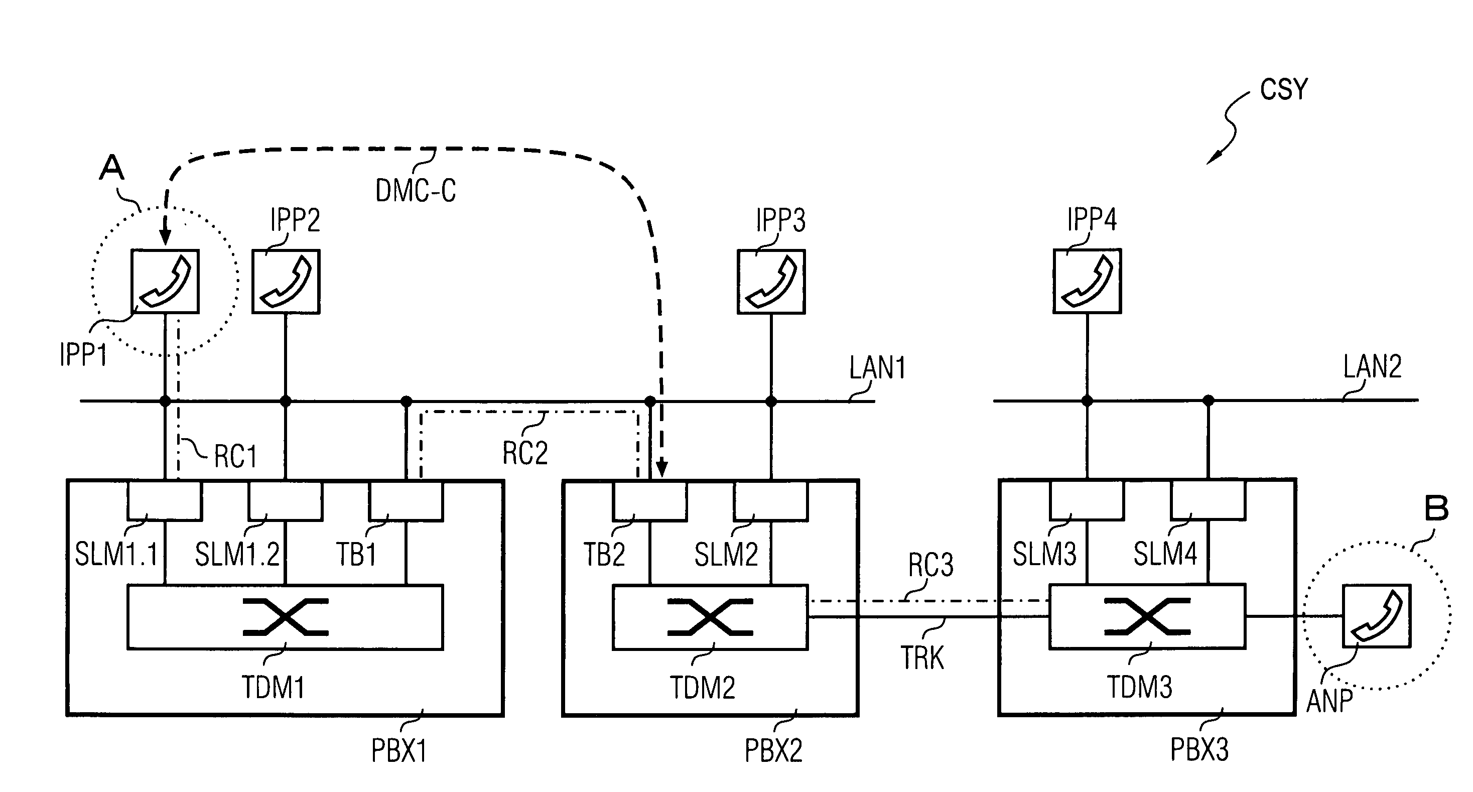
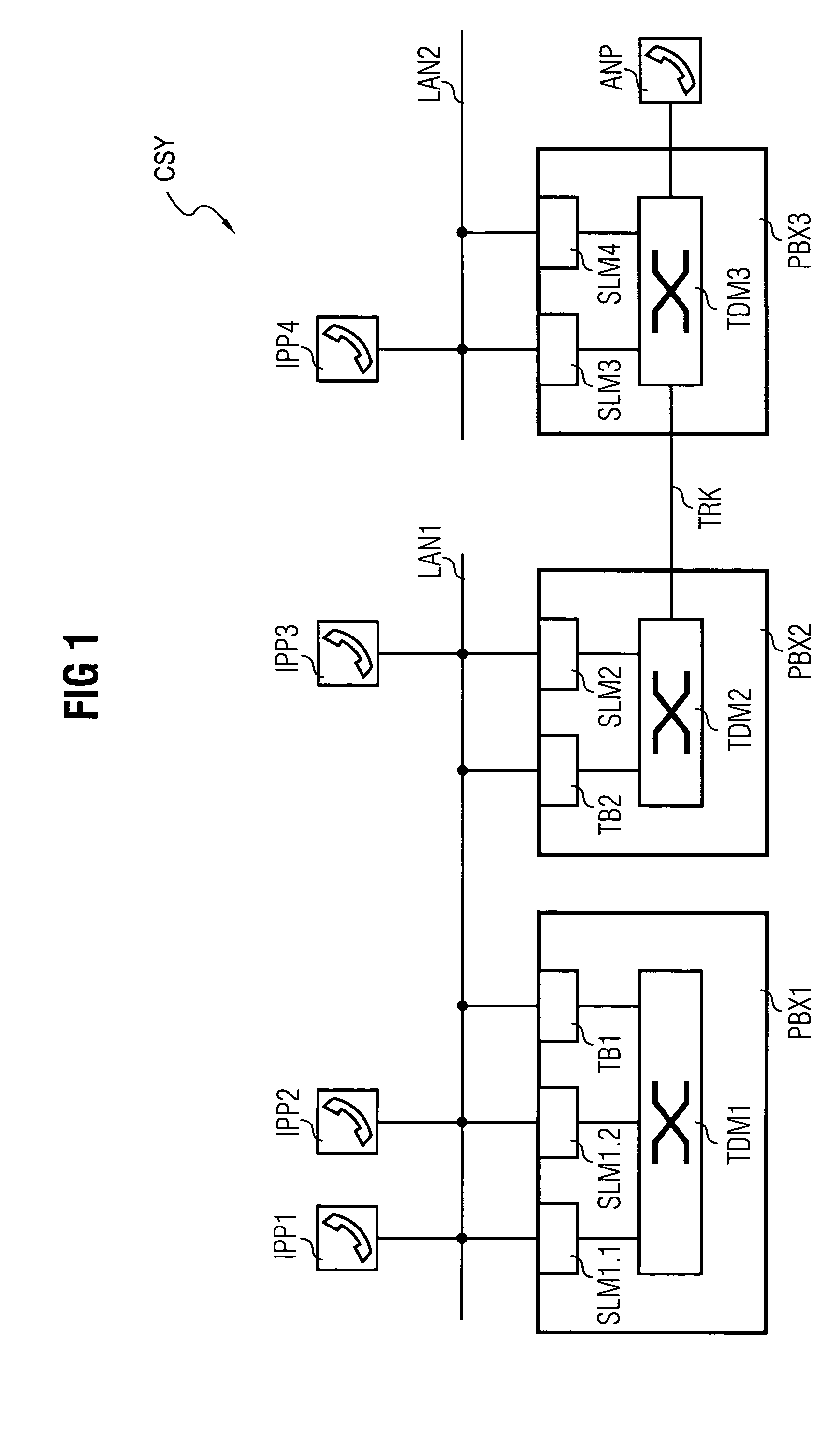
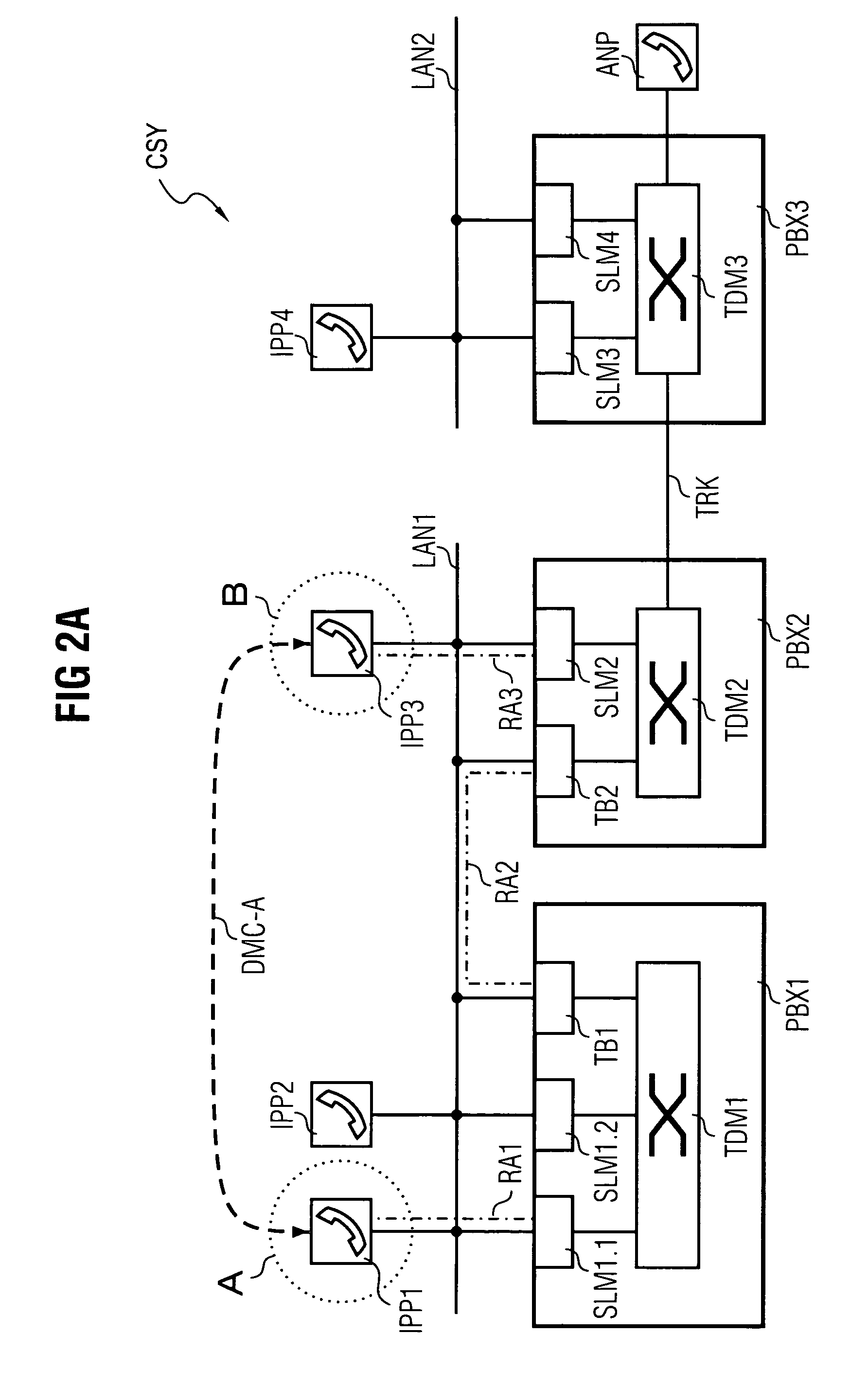
[0035]FIG. 1 shows a communication system CSY comprising an extract of functional components essential to the invention. Node units in the form of a first communication device PBX1, a second communication device PBX2 and a third communication device PBX3 are a major component of the communication system CSY.

[0036]The communication devices PBX1,PBX2,PBX3 operate internally according to a timeslot-oriented switching principle—often referred to in technical circles as >>Time Division Multiplex1,TDM2,TDM3.

[0037]The communication devices PBX1,PBX,PBX3 are in each case embodied with a circuit-switching switching matrix TDM1,TDM2,TDM3 and in each case connected both to one another and to a packet-oriented network.

[0038]The first and the second communication device PBX1,PBX2 are connected to a first packet-oriented network segment LAN1. The first packet-oriented network segment LAN1 is embodied alternatively as an intranet, corporate network, as a domain of a larger network or also as part ...


PUM


Abstract

The invention relates to a method for transmitting communication data in a communication system (CSY) between a calling first communication unit (IPPA) and a called second communication unit (IPPD), wherein, in a first step a primary connection is set up starting from the first communication unit (IPPA) via at least one node unit to the second communication unit (IPPD) with transmission of addressing data of the communication units (IPPA,IPPD) and node units participating in the setup of the primary connection. Following this, the first communication unit (IPPA) and / or a first node unit disposed along the primary connection which have a valid addressing data element are registered as the ingress node. Furthermore, the second communication unit (IPPD) and / or a last node unit disposed along the primary connection which have a valid addressing data element are registered as the egress node. With the embodiment of a secondary connection (DMC) between the egress and the ingress node via a network which is available in the communication system (CSY), communication data is finally transmitted via the secondary connection (DMC).

Description

CROSS REFERENCE TO RELATED APPLICATIONS[0001]This application claims priority to the German application No. 10354947.1 DE, filed Nov. 25, 2003 and which is incorporated by reference herein in its entirety.FIELD OF INVENTION[0002]The invention relates to a method for transmitting communication data in a preferably heterogeneous communication system.BACKGROUND OF INVENTION[0003]In contemporary communication systems it is known how to transmit user data, e.g. for voice or video communication, both by means of what is known as a circuit-switched technology and also via packet-oriented networks. Communication systems which support both a packet-oriented and a circuit-switching transmission technology are referred to in the following as >>convergent<< communication systems. As a result of the use of packet-oriented data transmission methods for communication systems of this type there are frequently losses in the quality of the user data to be transmitted, which losses are due...

Claims


Application Information

Patent Timeline
Patent Type & Authority Patents(United States)
IPC IPC(8): H04L12/66H04L29/06H04M7/00H04Q3/00
CPCH04M7/006H04M7/009H04M7/1245H04Q3/0016H04L65/80H04L65/1069H04Q2213/13196H04Q2213/1322H04Q2213/13389H04Q2213/13034
Inventor STAMPFL, ROBERTWILLE, KLAUSWINKLER, STEFFI
Owner UNIFY GMBH & CO KG
Learn More