Armored fiber optic assemblies and methods of making the same

a technology of armored fiber optic cables and fiber optic cables, applied in the direction of optics, fibre mechanical structures, instruments, etc., can solve the problems of time-consuming and expensive installation, add to the complexity and expense of installing metal-armored fiber optic cables, and conventional interlocking armor construction, etc., to achieve crush resistance and impact resistance.

Active Publication Date: 2010-04-20
CORNING OPTICAL COMM LLC
View PDF14 Cites 22 Cited by
  • Summary
  • Abstract
  • Description
  • Claims
  • Application Information

AI Technical Summary

Benefits of technology

[0009]The disclosure is directed to armored fiber optic assemblies having a dielectric armor along with methods for manufacturing the same. The dielectric armor can have an armor profile, thereby resembling conventional metal armored cable to the craft. Moreover, the dielectric armor provides additional crush and impact resistance to the optical fibers and / or fiber optic assembly therein. The dielectric armor is also advantageous to the craft since it provides the desired mechanical performance without requiring the time and expense of grounding like conventional metal armored cables. Additionally, armored fiber optic assemblies can have any suitable flame and / or smoke rating for meeting the requirements of the intended space; however, the assemblies may have outdoor applications or indoor / outdoor applications.

Problems solved by technology

However, there are disadvantages for this conventional interlocking armor construction.
For instance, fiber optic cables having a metallic armor require additional hardware and / or installation procedures for grounding the metallic armor to meet safety standards, thereby making installation time-consuming and expensive.
This adds to the complexity and expense of installing a metal-armored fiber optic cable.
Additionally, the metallic armor can be plastically deformed (i.e., permanently deformed) which can pinch the cable and cause elevated levels of optical attenuation.
Manufacturers have attempted to design dielectric armor cables to overcome the drawbacks of the conventional metallic armor constructions, but to date a commercial solution is lacking.
However, one skilled in the art would recognize this design does not provide the craft with all of the desired features.
Moreover, it can be difficult for the craft to recognize the cable of the '276 patent as an armored cable layered because it has a smooth outer surface, whereas conventional metal armored cables are easily identified by the craft as depicted by FIG. 1.

Method used


Image

  • Armored fiber optic assemblies and methods of making the same
  • Armored fiber optic assemblies and methods of making the same
  • Armored fiber optic assemblies and methods of making the same

Examples


Embodiment Construction

[0038]Reference is now made in detail to the present preferred embodiments of the invention, examples of which are illustrated in the accompanying drawings. Whenever possible, identical or similar reference numerals are used throughout the drawings to refer to identical or similar parts. It should be understood that the embodiments disclosed herein are merely examples with each one incorporating certain benefits of the present invention. Various modifications and alterations may be made to the following examples within the scope of the present invention, and aspects of the different examples may be mixed in different ways to achieve yet further examples. Accordingly, the true scope of the invention is to be understood from the entirety of the present disclosure in view of, but not limited to the embodiments described herein.

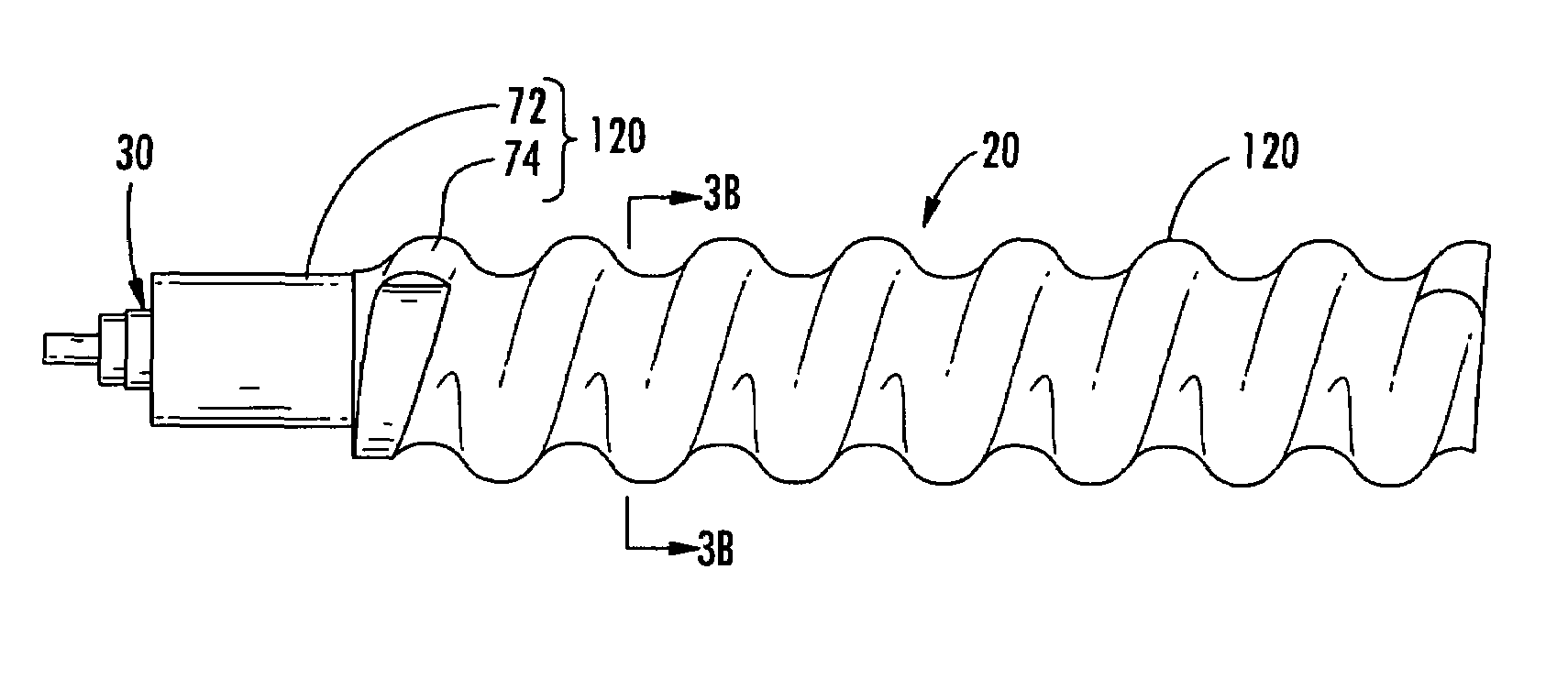
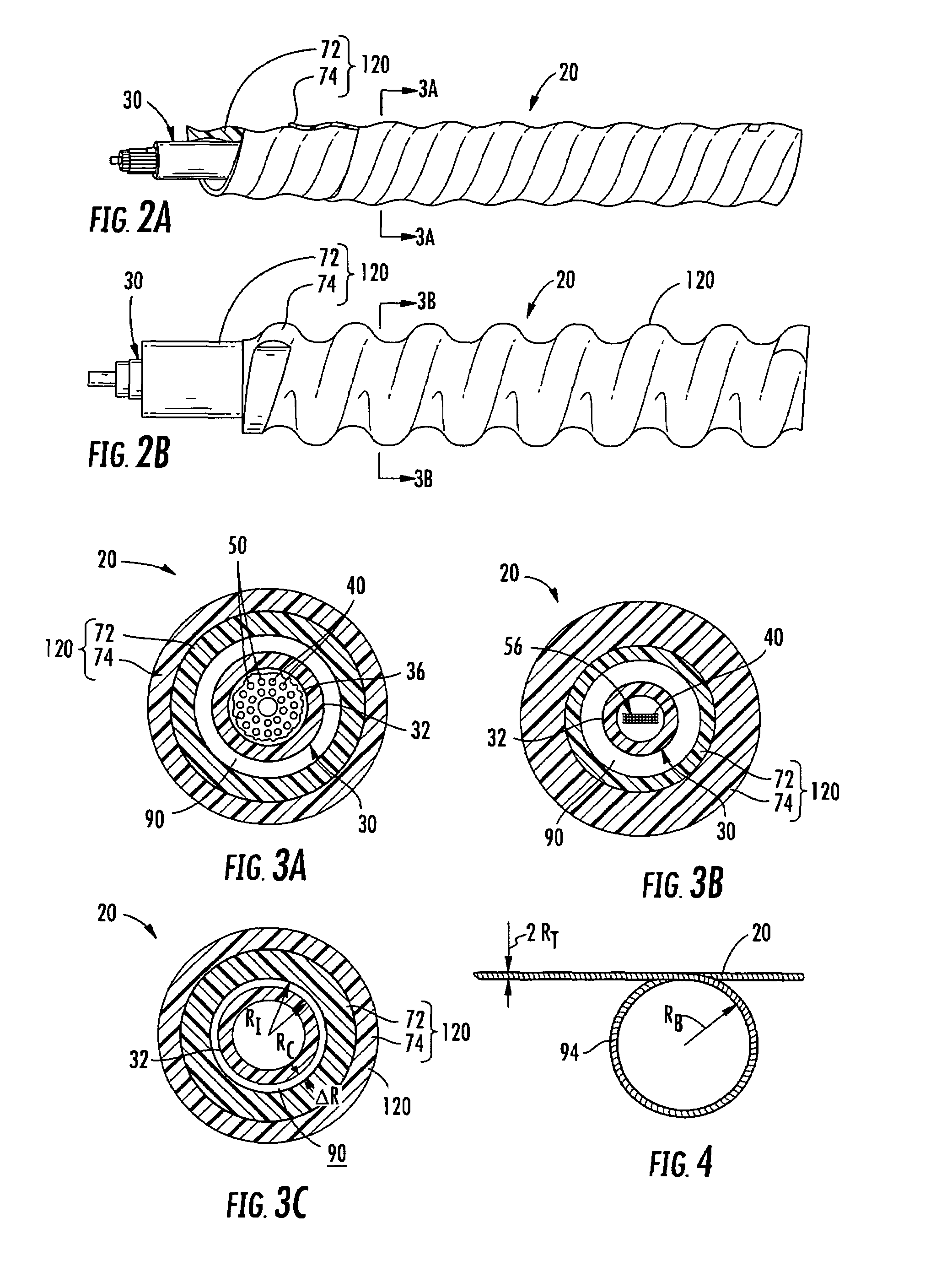
[0039]FIGS. 2A and 2B depict side cut-away views of two different armored fiber optic assemblies 20 having at least one optical fiber 40 disposed within a dielec...


PUM


Abstract

Armored fiber optic assemblies are disclosed that include a dielectric armor along with methods for manufacturing the same. The dielectric armor has an armor profile, thereby resembling conventional metal armored cable to the craft. The dielectric armor provides additional crush and impact resistance and the like for the optical fibers and/or fiber optic assembly therein. The dielectric armor is advantageous to the craft since it provides the desired mechanical performance without requiring the time and expense of grounding like conventional metal armored cables. Additionally, the armored fiber optic assemblies can have any suitable flame and/or smoke rating for meeting the requirements of the intended space.

Description

BACKGROUND[0001]1. Field of the Disclosure[0002]The present invention relates generally to optical fiber assemblies, and in particular relates to armored fiber optic assemblies having a dielectric armor along with methods of making the same.[0003]2. Technical Background[0004]Conventional fiber optic cables include optical fibers that conduct light for transmitting voice, video and / or data. The construction of fiber optic cables should preserve optical performance when deployed in the intended environment while also meeting the other additional requirements for the environment. For instance, indoor cables for riser and / or plenum spaces may require certain flame-retardant ratings to meet the demands of the space. In other words, these flame-retardant ratings are addition to mechanical requirements or desired characteristics for the space. Mechanical requirements or characteristics such as crush performance, permissible bend radii, temperature performance, or the like are desired to in...

Claims


Application Information

Patent Timeline
Patent Type & Authority Patents(United States)
IPC IPC(8): G02B6/44
CPCG02B6/443G02B6/4429
Inventor BOHLER, GREGORY B.GREENWOOD, III, JULIAN L.GREER, KEITH A.MILLER, ALLEN M.NICHOLSON, WESLEY B.SLAN, KIMBERLY D.
Owner CORNING OPTICAL COMM LLC
Why Eureka
Try Eureka