Fixing device, and image forming apparatus using the fixing device

a fixing device and image forming technology, applied in the field of fixing devices, can solve the problems of unfixed toner layers adhesion, hot offset problem, cold offset phenomenon, etc., and achieve the effect of high quality toner images

Inactive Publication Date: 2010-04-20
RICOH KK
View PDF39 Cites 62 Cited by
  • Summary
  • Abstract
  • Description
  • Claims
  • Application Information

AI Technical Summary

Benefits of technology

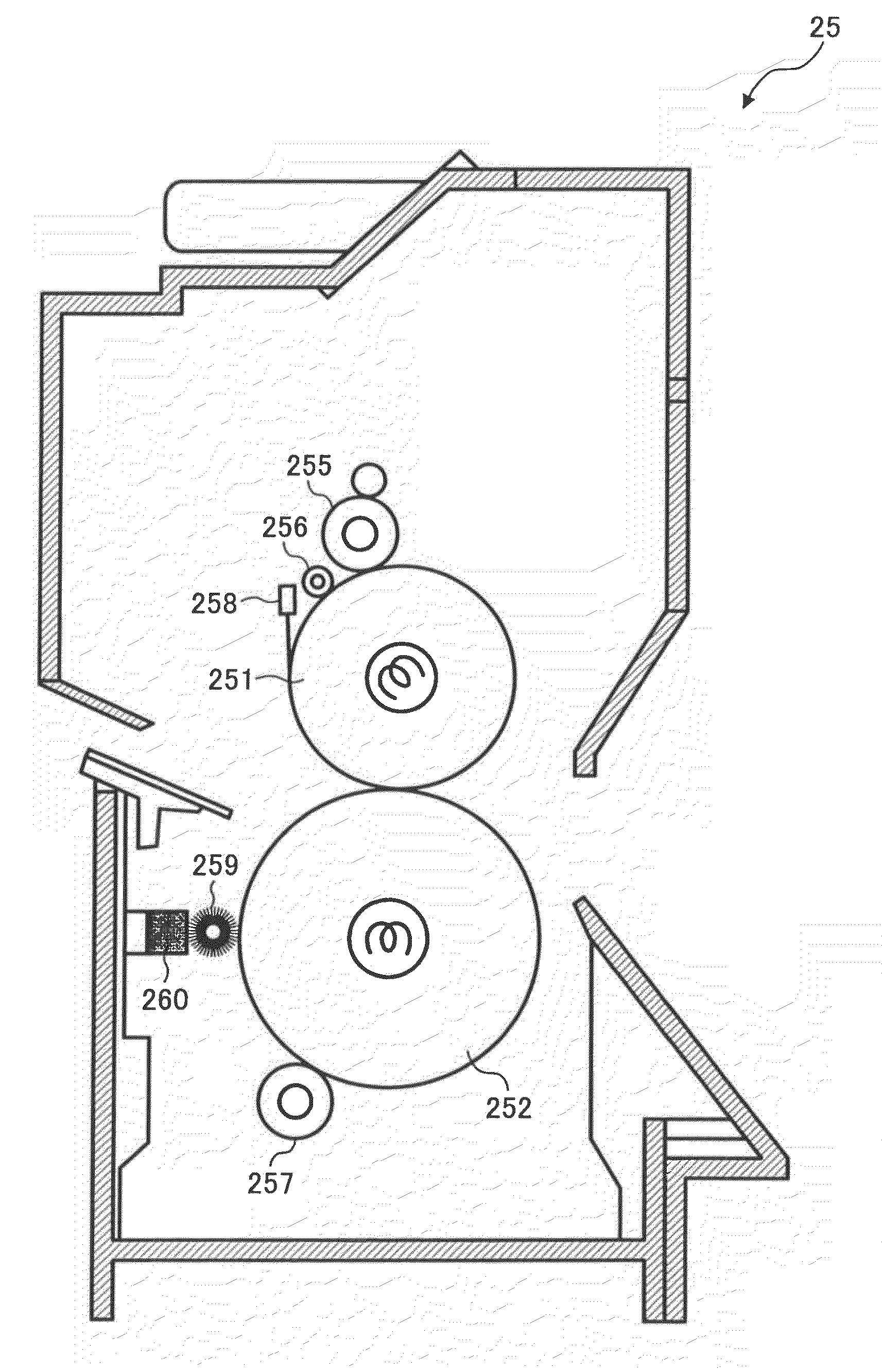
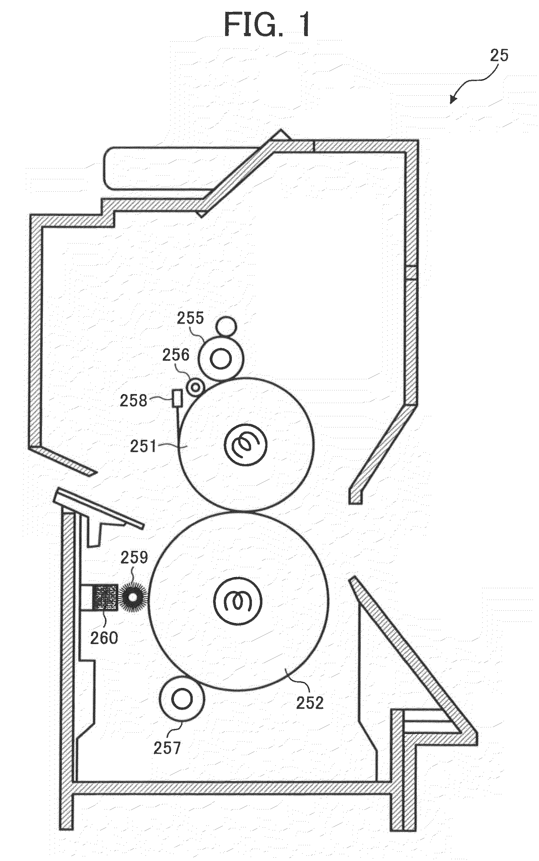
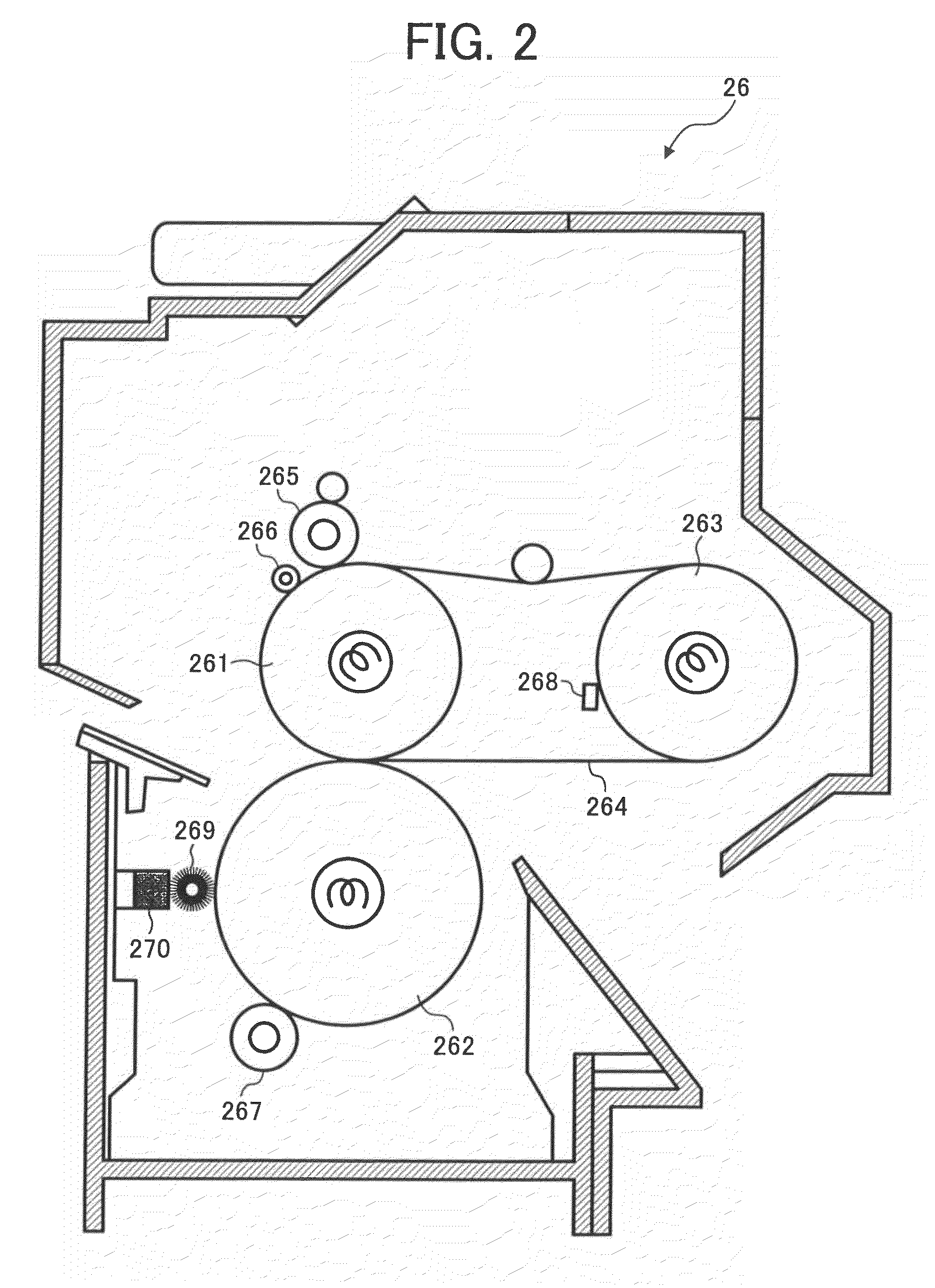
[0025]Accordingly, an object of the present invention is to provide a fixing device which includes a cleaning member and which can produce high quality toner images without causing the toner re-transferring problem in that toner particles adhered to the cleaning device is re-transferred to the fixing member and pressing member.
[0026]Another object of the present invention is to provide an image forming apparatus which can produce high quality toner images without causing undesired images such as offset images.

Problems solved by technology

However, the heat roller fixing methods tends to cause an offset problem in that part of a fused toner image, which contacts the surface of a heating roller under pressure, is adhered and transferred to the surface of the heating roller, and then the part of the toner image is re-transferred to an undesired portion of the sheet itself or the following sheet of the recording material.
Therefore, the uppermost toner layer is heated to a high temperature, and thereby a hot offset problem tends to be caused.
If the temperature of the heating roller is decreased to avoid the hot offset problem, another problem in that the lowermost toner layer is not fully fixed, resulting in occurrence of a cold offset phenomenon in that the unfixed toner layer adheres to the heating roller.
However, the shearing force applied to the toner image to be fixed is increased, and thereby another problem in that the recording sheet is wound around the heating roller, resulting in jamming of the recording sheet.
Alternatively, even when such a jamming problem does not occur, a problem in that the resultant image has a white scratch image because the toner image is scratched with a separation pick which is configured to separate the recording material from the heating roller tends to occur.
In addition, when the fixing pressure is high, problems in that fine line images are widened, and / or toner particles in the toner image are scattered tend to occur, resulting in deterioration of image qualities.
When such a toner is used at a low fixing speed, the hot offset problem tends to occur.
Namely, there is no toner which can be used in a wide fixing speed range.
When such a toner having a small particle diameter is used, the fixing properties of half tone images deteriorate particularly when the fixing speed is relatively high.
Therefore, the offset problem easily occurs at the projected portion.
Thus, the resultant half tone image tends to have poor image qualities.
As mentioned above, such a fixing device tends to cause the offset problem in that the toner image on the recording material is adhered to the heating roller, and the toner image is re-transferred to an undesired portion of the sheet or the following sheet of the recording material.
When such offset phenomenon is caused, the toner image adhered to the heating roller is also transferred to the pressing roller contacting the heating roller, and thereby a problem in that a toner image is re-transferred to the backside of the recording sheet or the following recording sheet is also caused.
However, even though such a heating roller is used, it is impossible to perfectly prevent occurrence of the offset problem when the environmental conditions and the recording materials are changed.
Therefore, the image forming apparatus has a problem in that the temperature of the heating roller varies in the width direction thereof.
However, this problem is not yet solved, namely it is difficult to uniformly heat the entire of such a heating roller to a predetermined fixing temperature because of the structural limitation and cost limitation.
When the temperature of a heating roller becomes uneven in the width direction thereof, good fixing properties cannot be stably obtained and the offset problem tends to be caused.
In addition, the life of the heating roller is shortened due to heat deterioration of the heating roller.
In particularly, when the polymerized toner disclosed in, for example, JP-A 2000-292981 is used, a problem in that toner blocks adhered to and accumulated on a cleaning member are re-melted and transferred to a recording sheet occurs.
When a toner prepared by a pulverization method is used, such a problem hardly occurs.
This problem is typically caused when recording sheets with a narrow width are used.
Therefore, the temperature of both the end portions of the heating rollers is excessively increased, and thereby the toner blocks present on both end portions of the cleaning member are fused and re-transferred to the pressing roller and heating roller.

Method used


Image

  • Fixing device, and image forming apparatus using the fixing device
  • Fixing device, and image forming apparatus using the fixing device
  • Fixing device, and image forming apparatus using the fixing device

Examples


manufacturing example 1

Synthesis of Modified Polyester Resin (A-1)

[0303]The following components were contained in a reaction vessel equipped with a condenser, a stirrer and a nitrogen introducing tube and reacted for 8 hours at 230° C. under normal pressure.

[0304]

Ethylene oxide adduct (2 mole) of bisphenol A358 partsPropylene oxide adduct (2 mole) of bisphenol A381 partsIsophthalic acid200 partsTerephthalic acid127 partsDibutyl tin oxide 2 parts

[0305]The reaction was further continued for 5 hours under a reduced pressure of from 10 to 15 mmHg while removing water generated.

[0306]Thus, a polyester prepolymer having a hydroxyl value of 25 mgKOH / g and an acid value of 0.9 mgKOH / g was prepared.

[0307]After the reaction product including the polyester prepolymer was cooled to 80° C., 364 parts of ethyl acetate and 98 parts of isophoron diisocyanate were added thereto, and the mixture was reacted for 2 hours.

[0308]Thus, an ethyl acetate solution of a modified polyester resin (A-1) having a weight average molecu...

manufacturing example 2

Preparation of Blocked Amine Compound (B)

[0309]In a reaction vessel equipped with a stirrer and a thermometer, 30 parts of isophorone diamine and 70 parts of methyl ethyl ketone were contained and reacted for 5 hours at 50° C. to prepare a blocked amine compound (B).

manufacturing example 3

Preparation of Unmodified Polyester Resin (1)

[0310]The following components were contained in a reaction vessel equipped with a condenser, a stirrer and a nitrogen introducing tube to perform a polycondensation reaction for 8 hours at 230° C. under normal pressure.

[0311]

Ethylene oxide adduct (2 mole) of bisphenol A229 partsPropylene oxide adduct (3 mole) of bisphenol A529 partsTerephthalic acid208 partsAdipic acid 46 partsDibutyl tin oxide 2 parts

[0312]The reaction was further continued for 5 hours under a reduced pressure of from 10 to 15 mmHg. Then 44 parts of trimellitic anhydride were added thereto and the mixture was reacted for 1.8 hours at 180° C. under normal pressure. Thus, an unmodified polyester resin (1) was prepared.

[0313]The unmodified polyester resin (1) had a number average molecular weight (Mn) of 2,500, a weight average molecular weight (Mw) of 6,700, a peak molecular weight of 5,000, a glass transition temperature of 43° C., and an acid value of 25 mgKOH / g.


PUM


Abstract

An image forming apparatus including an image bearing member; a charger; a light irradiator; a developing device; a transfer device; an image bearing member's cleaner; and a fixing device, wherein the fixing device includes a fixing member configured to fix a toner image upon application of heat and pressure thereto; a pressing member configured to press the recording material toward the fixing member; and a cleaning member configured to clean a surface of the fixing member and / or the pressing member, wherein the cleaning member has an outermost layer including a reactive material which increases viscoelasticity of a binder resin of the toner by reacting with the binder resin.

Description

CROSS-REFERENCE TO RELATED APPLICATIONS[0001]The present application is a continuation of U.S. application Ser. No. 11 / 058,278 filed on Feb. 16, 2005, now U.S. Pat. No. 7,437,111 and claims priority to JP2004-039107 filed on Feb. 16, 2004, JP2004-218496 filed on Jul. 27, 2004, and JP2004-222780 filed on Jul. 30, 2004, the entire contents of each of which are hereby incorporated by reference.BACKGROUND OF THE INVENTION[0002]1. Field of the Invention[0003]The present invention relates to a fixing device for fixing a toner image. More particularly, the present invention relates to a fixing device for use in electrophotographic image forming apparatus, such as copiers, facsimile machines and laser printers, which fixes toner images formed by a direct or indirect monochrome electrophotographic developing method or a direct or indirect full color electrophotographic developing method. In addition, the present invention also relates to an image forming apparatus using the fixing device.[00...

Claims


Application Information

Patent Timeline
Patent Type & Authority Patents(United States)
IPC IPC(8): G03G15/20G03G21/00G03G21/20
CPCG03G15/2053G03G15/2025G03G21/00G03G2221/0005
Inventor YAMADA, HIROSHISASAKI, FUMIHIROEMOTO, SHIGERUOKAMOTO, JUNOHTANI, SHINJIHIGUCHI, HIROTOSHIMOTA, NAOHITOYAGI, SHINICHIROAWAMURA, JUNICHISUZUKI, TOMOMITOMITA, MASAMINANYA, TOSHIKIYAMAGUCHI, YOSHIKI
Owner RICOH KK
Why Eureka
Try Eureka