Method for making transmission electron microscope grid

a technology of transmission electron microscope and grid, which is applied in the direction of electrical discharge tubes, semiconductor devices, electrical apparatus, etc., can solve the problems of difficult application of cnts in tem grids, amorphous carbon films can negatively affect tem imaging,

Active Publication Date: 2009-12-24
TSINGHUA UNIV +1
View PDF4 Cites 48 Cited by
  • Summary
  • Abstract
  • Description
  • Claims
  • Application Information

AI Technical Summary

Problems solved by technology

In practical application, when the size of an observed particle is less than 5 nanometers (nm), the amorphous carbon film can negatively impact TEM imaging.
However, there has been difficulty in applying CNTs in TEM grids.

Method used


Image

  • Method for making transmission electron microscope grid
  • Method for making transmission electron microscope grid
  • Method for making transmission electron microscope grid

Examples


Embodiment Construction

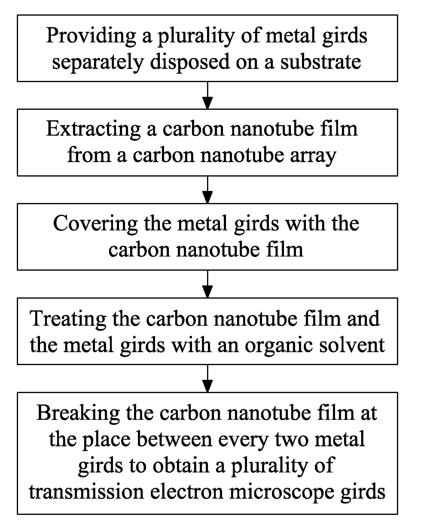
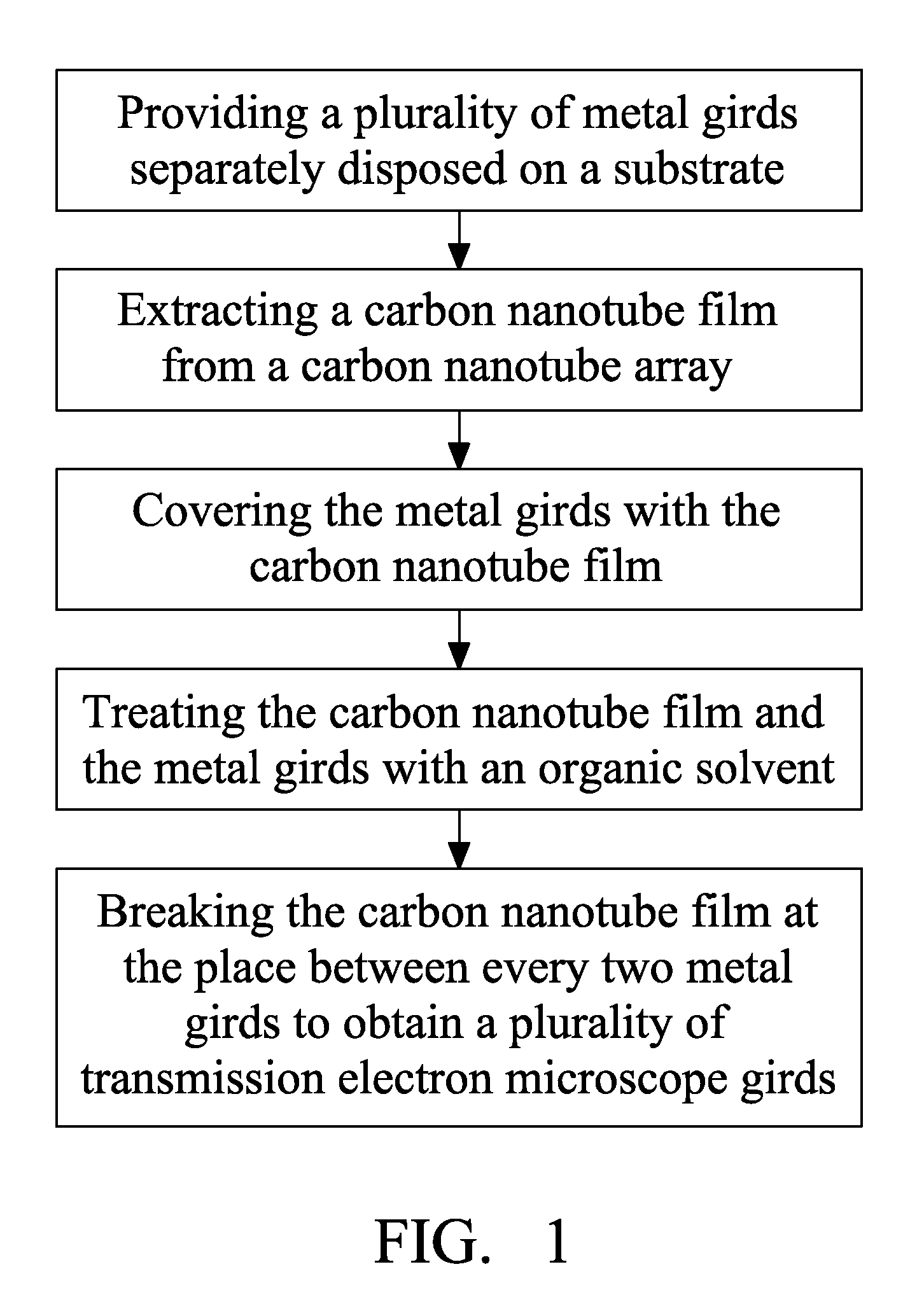
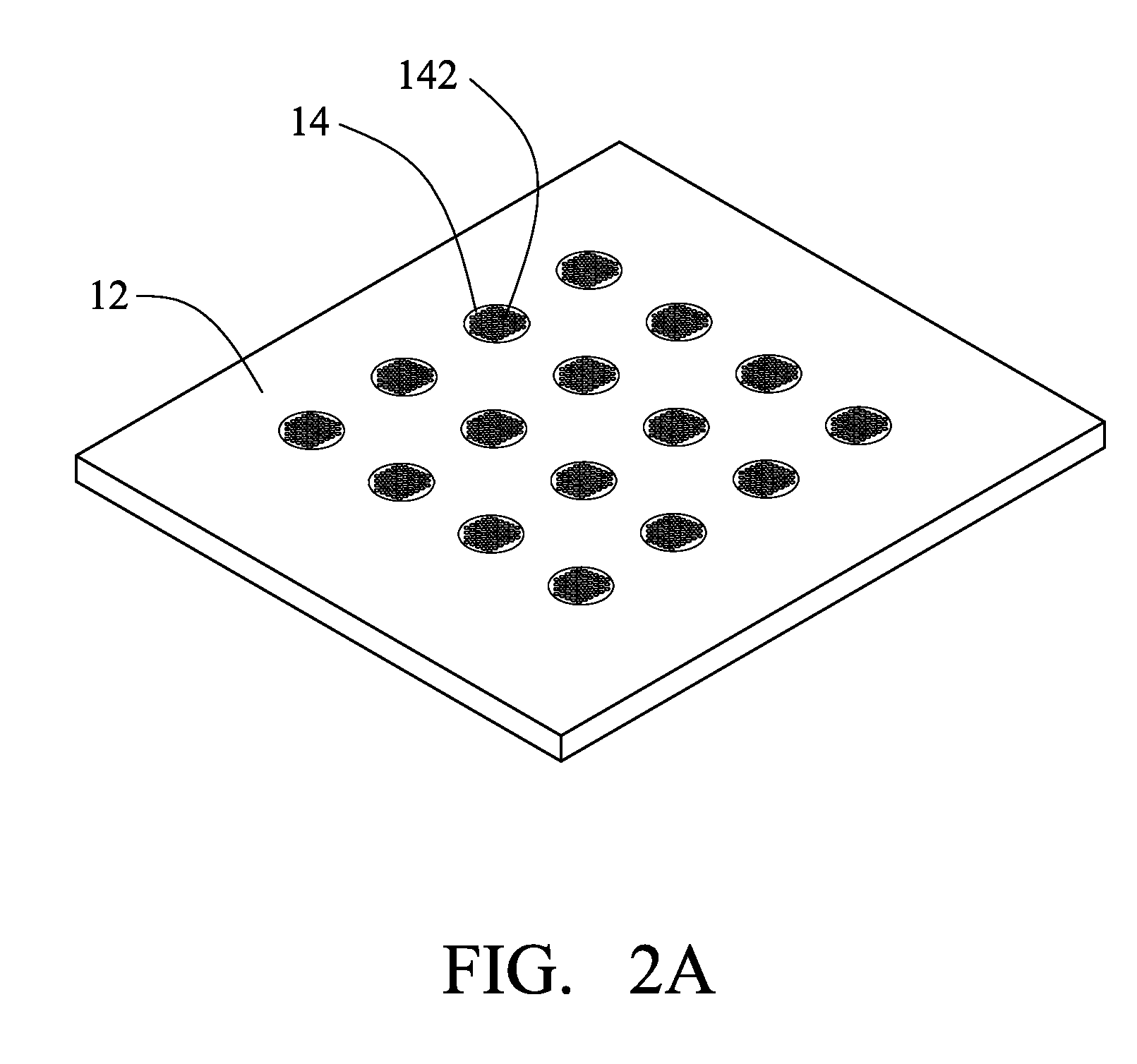
[0016]Reference will now be made to the drawings to describe various embodiments of the present method for fabricating a TEM grid, in detail.

[0017]Referring to FIG. 1 and FIGS. 2A-2D, a method for fabricating a TEM grid includes the steps of: (a) providing an array of carbon nanotubes (CNTs). In the present embodiment, a super-aligned array of CNTs is used.

[0018]In step (a), a CNT array be formed by the substeps of: (a1) providing a flat and smooth substrate; (a2) forming a catalyst layer on the substrate; (a3) annealing the substrate with the catalyst at a temperature in the approximate range from 700° C. to 900° C. in air for about 30 to 90 minutes; (a4) heating the substrate with the catalyst at a temperature in the approximate range from 500° C. to 740° C. with a protective gas therein; and (a5) supplying a carbon source gas for about 5 to 30 minutes and growing a super-aligned array of the CNTs from the substrate.

[0019]In step (a1), the substrate can be a P-type silicon wafer, ...


PUM

PropertyMeasurementUnit
poweraaaaaaaaaa
angleaaaaaaaaaa
temperatureaaaaaaaaaa

Abstract

A method for making transmission electron microscope gird is provided. An array of carbon nanotubes is provided and drawing a carbon nanotube film from the array of carbon nanotubes. A substrate has a plurality of spaced metal girds attached on the substrate. The metal girds are covered with the carbon nanotube film and treating the carbon nanotube film and the metal girds with organic solvent. A transmission electron microscope (TEM) grid is obtained by removing remaining CNT film.

Description

BACKGROUND[0001]1. Field of the Disclosure[0002]The disclosure relates to a method for making an electron microscope grid, and particularly to a method for making a transmission electron microscope grid.[0003]2. Description of Related Art[0004]Transmission electron microscopy (TEM) is one of the most important techniques available for the detailed examination and analysis of the nano-structural characteristics of many materials. The TEM technique provides high resolution imaging and material analysis of thin specimens in the range of 0.01-0.2 microns (μm). In a conventional method for specimen preparation, a metal grid such as a copper or nickel grid covered by a porous organic membrane is provided, then evaporation is used to deposit an amorphous carbon film on the porous organic membrane. In practical application, when the size of an observed particle is less than 5 nanometers (nm), the amorphous carbon film can negatively impact TEM imaging.[0005]Carbon nanotubes (CNTs) have a hi...

Claims


Application Information

Patent Timeline
Patent Type & Authority Applications(United States)
IPC IPC(8): H01L21/268
CPCH01J37/20H01J2237/2802H01J2237/2007Y10S438/96
Inventor ZHANG, LI-NACHEN, ZHUOFENG, CHENLIU, LIANGJIANG, KAI-LILI, QUN-QINGFAN, SHOU-SHAN
Owner TSINGHUA UNIV
Why Eureka
Try Eureka