Displacement sensor

Active Publication Date: 2006-12-19
ORMON CORPORATION
View PDF14 Cites 49 Cited by
  • Summary
  • Abstract
  • Description
  • Claims
  • Application Information

AI Technical Summary

Benefits of technology

[0032]Therefore, the time period required for reading out the electric charges for each frame can be reduced by not reading the electric charges from the back optically black pixel region, and this allows successive shots to be taken at high speed.
[0033]In this electric charge transfer protocol, the front optically black pixel region handling process may include a process of repeatedly performing a plurality of stages of consecutive vertical transfer for each horizontal interval over one or a plurality of horizontal intervals. At this time, the process of performing a plurality of stages of consecutive vertical transfer for each horizontal interval may be performed during the horizontal interval while the transfer of the horizontal shift register is being suspended during the horizontal interval. Thereby, the unnecessary image which is obtained from the front optically black pixel region can be expelled to the horizontal shift register at high speed. In the electric charge transfer protocol mentioned above, the photosensitive pixel region handling process may comprise a process of performing one or a plurality of stages of consecutive vertical transfer and performing consecutive horizontal transfer of a number of stages corresponding to the number of pixels in each horizontal line one after the other in a time shift within a horizontal interval. Thereby, the stored electric charges are put into the video signal every time the transfer of electric charges for one or a plurality of horizontal lines have been transferred, and this simplifies the image processing based on the video signa

Problems solved by technology

Because the light receiving device 505 of the conventional optical displacement sensor consisted of a PSD or one-dimensional CCD that can capture only one-dimensional information, a highly complicated scanning mechanism was necessary to effect a relative movement between the sensor head 500 and the measurement object 600 as shown in FIG. 29, and a problem has been pointed out t

Method used


Image

  • Displacement sensor
  • Displacement sensor
  • Displacement sensor

Examples


Example

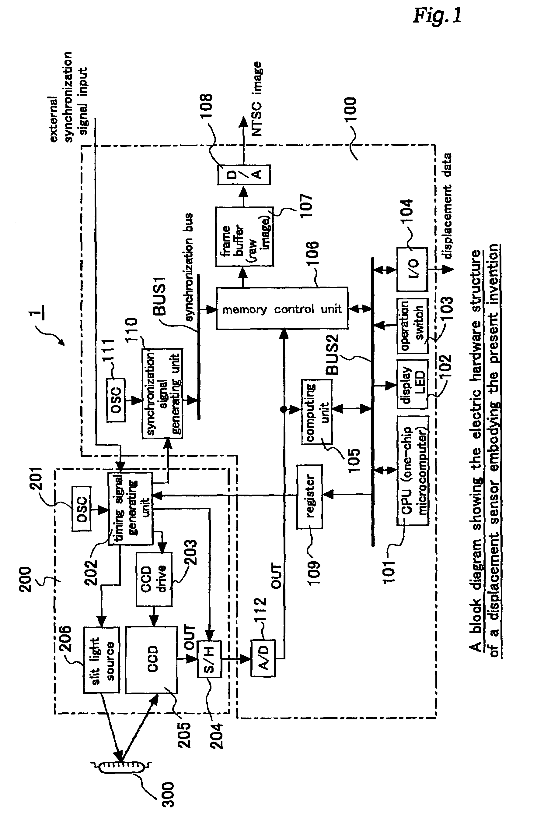
[0090]FIG. 1 is a block diagram showing the electric hardware structure of a displacement sensor embodying the present invention.

[0091]Referring to the drawing, this displacement sensor 1 essentially consists of a sensor head unit 200 forming an imaging unit for capturing the image of the surface of a measurement object 300 showing a sectional light image thereon from such an angle that the light image may change its position on the surface of the measurement object 300 with the displacement of the measurement object 300, and a sensor main unit 100 forming an image processing unit for computing the measurement object displacement and producing it as displacement data by processing the image obtained by the sensor head unit 200.

[0092]The sensor head unit 200 produces a required timing signal according to an oscillator (OSC 201) and a transfer protocol table stored in a register 109 provided in the sensor main unit 100, and forwards it to a CCD drive 203 and a slit light source 206. T...


PUM


Abstract

A displacement sensor comprising an imaging unit and an image processing unit. The imaging unit comprises a two dimensional imaging device and a drive control unit. The two dimensional imaging device includes a group of light receiving pixels arranged in a matrix so as to correspond to a field of view of a standard imaging unit, a plurality of vertical shift registers corresponding to different columns of the pixels, and a horizontal register for receiving the outputs of the vertical shift registers from top stages thereof, a photosensitive pixel region being defined in a prescribed horizontal band having a sufficiently narrower width than that would be provided by the total number of horizontal lines and interposed between a front optically black pixel region and a back optically black pixel region. The drive control unit controls, according to a commanded electric charge transfer protocol, a feeding of signal electric charges from each light receiving pixel to the vertical shift register of a corresponding column, a vertical transfer of signal electric charges in the vertical shift register of each column, and a horizontal transfer of signal electric charges in the horizontal shift register. The image processing unit comprises electric charge transfer protocol command means for giving an electric charge transfer protocol to the drive control unit of the imaging unit in dependence of a content of the image process.

Description

TECHNICAL FIELD[0001]The present invention relates to a displacement sensor for measuring a displacement of an object by using a light section method, and producing the measured value as it is or producing a determination result by comparing the measured value with a reference value, and in particular to a displacement sensor which allows a various modes of measurement to be performed using a two dimensional imaging device with elongated field of view as a light receiving device.BACKGROUND OF THE INVENTION[0002]An optical system of a sensor head of a conventional optical displacement sensor is shown in FIG. 28. In the drawing, numeral 500 denotes a sensor head unit, numeral 501 denotes a laser diode for emitting a sectional light for the light sectional method, numeral 502 denotes a slit for making the cross section of the sectional light into a linear shape, numeral 503 denotes a light emitting lens, numeral 504 denotes a light receiving lens, numeral 505 denotes a light receiving ...

Claims


Application Information

Patent Timeline
IPC IPC(8): H04N5/217H04N7/12H04N9/64G01B11/00G01B11/25
CPCG01B11/002G01B11/25G06T7/0057G06T7/521
Inventor KAWACHI, MASAHIROOKADA, MICHITOSHISHIMADA, KOJIOBA, HITOSHIYONEDA, SATOSHI
Owner ORMON CORPORATION
Why Eureka
Try Eureka