Sealed plug connection through a partition wall and method of fitting

a technology of sealing plugs and partition walls, applied in the direction of connection contact member materials, coupling device connections, coupling parts, etc., can solve problems such as failure of plug connections, and achieve the effect of increasing the security of connections

Active Publication Date: 2010-04-27
TE CONNECTIVITY GERMANY GMBH
View PDF23 Cites 17 Cited by
  • Summary
  • Abstract
  • Description
  • Claims
  • Application Information

AI Technical Summary

Benefits of technology

[0004]It is accordingly an object of the invention to provide a plug connection and a method of fitting the same, wherein the plug connection has an improved seal positioned at a partition wall and a sealing member positioned in a connection region in order to increase security of the connection.
[0005]A further object of the invention is to provide a plug connection and a method of fitting the same, wherein at least one plug of the plug connection can be fixed as easily as possible on a partition wall and fitting errors can easily be detected.
[0006]The present invention is based on the fundamental idea that the undesirable penetration of moisture into an interior of a plug connection can be avoided if a connection region between a clamping device and at least one plug of the plug connection is sealed by a sealing member positioned on a bearing projection. According to an advantageous embodiment, the clamping device comprises at least one actuating projection which co-operates with a socket arranged on one of the plugs, to clamp the plug. The force applied during clamping can easily be converted into a clamping force in this way.

Problems solved by technology

However, this known clamping device is accompanied by the problem that moisture can penetrate at joints between the clamping device and the plugs, which can lead to failure of the plug connection.

Method used


Image

  • Sealed plug connection through a partition wall and method of fitting
  • Sealed plug connection through a partition wall and method of fitting
  • Sealed plug connection through a partition wall and method of fitting

Examples


first embodiment

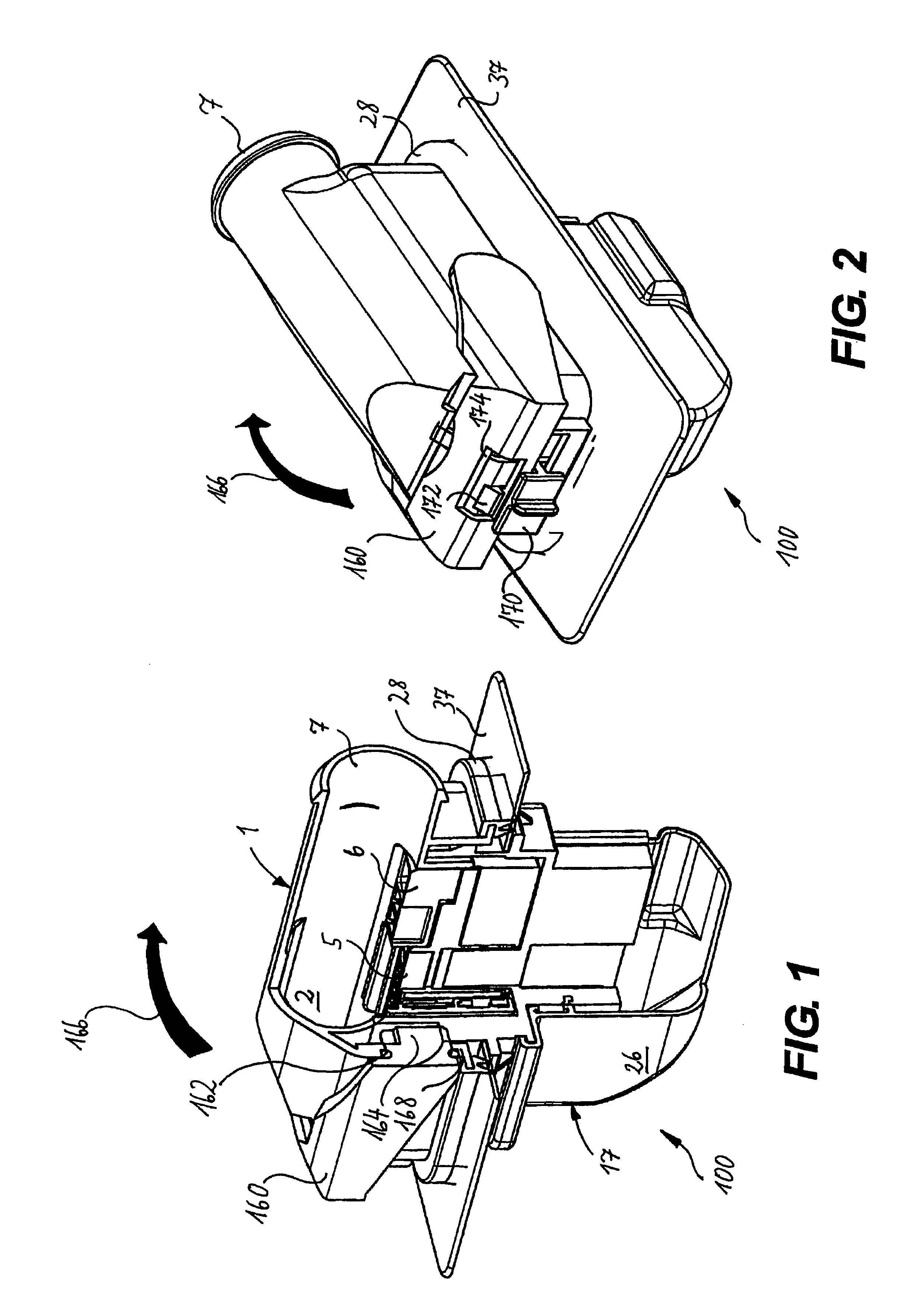
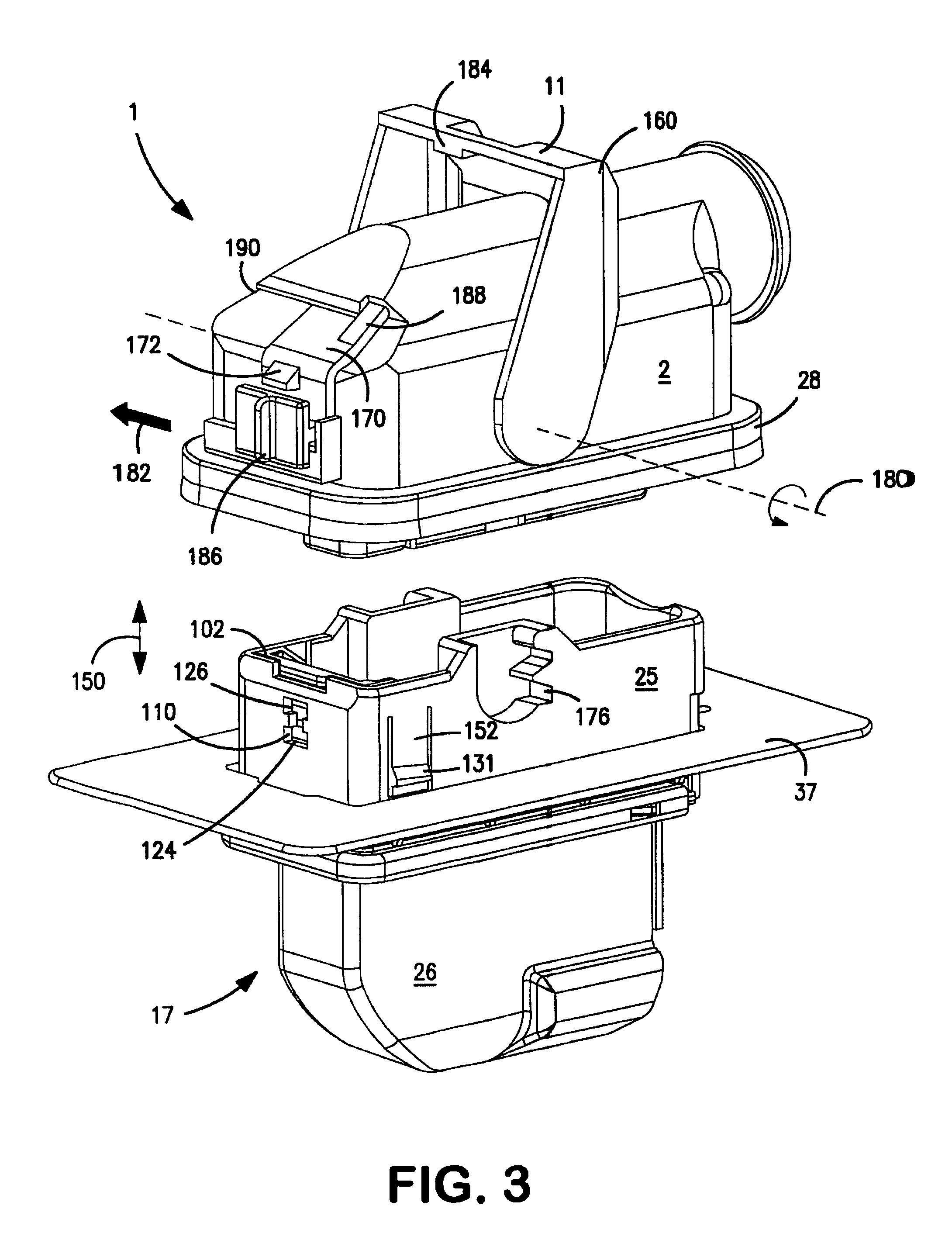
[0053]FIGS. 1-6 show a plug connection 100 according to the invention. As shown in FIG. 1, the plug connection 100 comprises a first plug 1 and a second plug 17. The second plug 17 is fitted in a partition wall 37. According to the present embodiment, the second plug 17 is a pin-type plug and the first plug 1 is a corresponding socket-type plug, however, this arrangement is not essential to the present invention as the arrangement could also be reversed.

[0054]According to the invention, the first plug 1 is sealed from the partition wall 37 by means of a peripheral seal 28. As will be described hereinafter with reference to FIGS. 3 and 4, the plug connection 100 according to the invention comprises a clamping device which, in a final fitted position shown in FIG. 1, draws the first and second plugs 1, 17 together with the partition wall 37 therebetween. According to a first embodiment of the invention, the clamping device is formed as a locking lever 160. The first plug 1 comprises a...

second embodiment

[0072]the plug connection 100 according to the invention will now be described with reference to FIGS. 7 to 16.

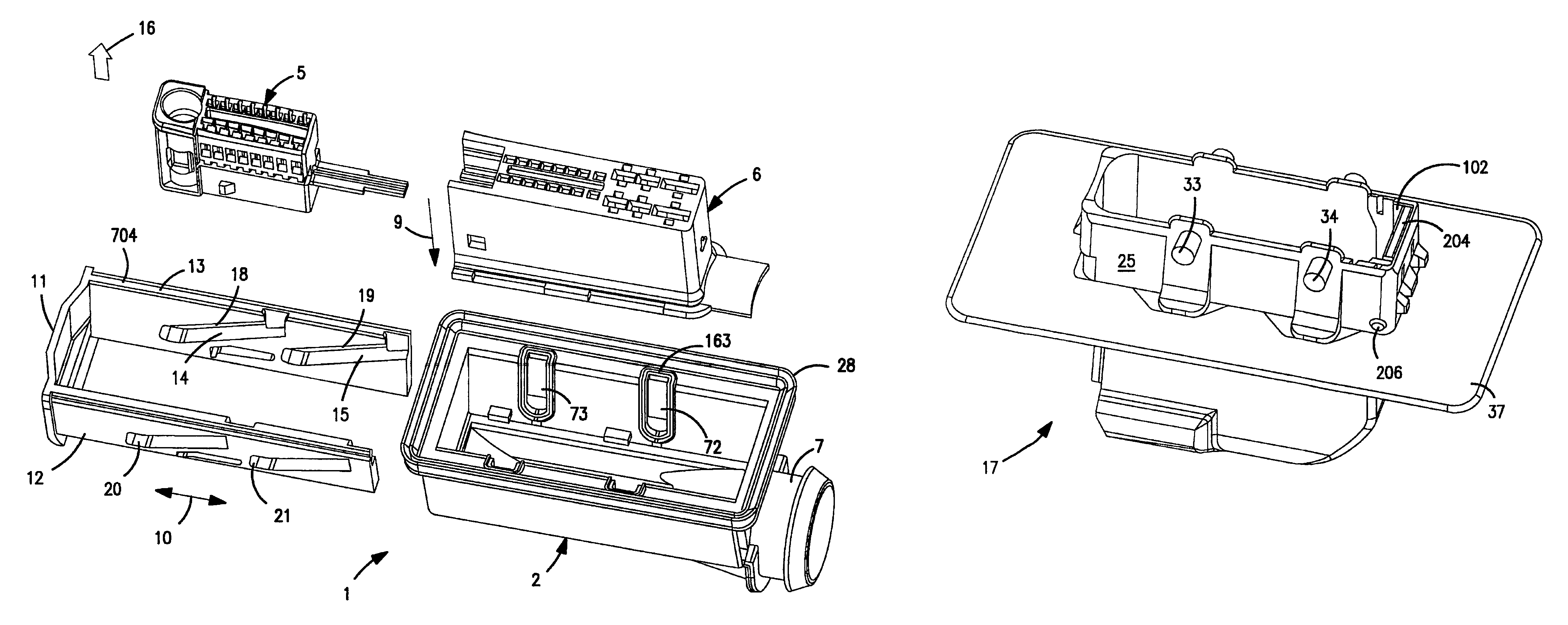
[0073]Referring to FIG. 7, the first plug 1 according to the second embodiment comprises a sliding device 704, instead of the clamping device configured as the locking lever 160, for clamping the first and second plugs 1, 17 together. The sliding device 704 is accommodated displaceably in the first plug housing 2 in a direction of arrow 10. The sliding device 704 comprises an actuating surface 11, to which a displacement force can be applied for displacing the sliding device 704.

[0074]The sliding device 704 comprises side elements 12, 13. As shown in FIG. 7, respective upper guide rails 14 and lower guide rails 15 are provided in the side elements 12, 13. The upper and lower guide rails 14, 15 are formed, for example, as guide recesses in this embodiment of the invention.

[0075]In FIG. 7, a proposed direction for plugging together the first plug 2 and the second plug 17 is i...


PUM


Abstract

A plug connection comprises a first plug having a seal and a second plug configured for fitting in an opening in a partition wall. The second plug is mateable with the first plug such that the seal substantially surrounds the opening in the partition wall. A clamping device is provided on the first plug and is configured for drawing the first plug into engagement with the second plug. The clamping device engages with the second plug at a connection region. The connection region is provided with a sealing member configured to seal the connection region between the clamping device and the second plug.

Description

FIELD OF THE INVENTION[0001]The present invention relates to a plug connection for producing at least one electrical connection through an opening in a partition wall. The plug connection, which is also known as a through plug, comprises a first and a second plug, which can be plugged together, and at least one of the plugs can be sealed from the partition wall by means of a seal that surrounds the opening. The invention relates, in particular, to a plug connection, wherein at least one of the plugs of said connection comprises a clamping device which can be engaged with the other plug and enables the two plugs to be drawn permanently in the direction in which they are plugged together with the partition wall therebetween. The invention also relates to a method of fitting for producing an electrical plug connection of this type.BACKGROUND OF THE INVENTION[0002]With a known generic plug of the type shown, for example, in published international patent application WO 2004 / 047234 A1, t...

Claims


Application Information

Patent Timeline
Patent Type & Authority Patents(United States)
IPC IPC(8): H01R13/62H01R13/52H01R13/629H01R13/74
CPCH01R13/5202H01R13/62911H01R13/74H01R13/62944H01R13/62927H01R13/741H01R13/62955
Inventor GIMBEL, MARKUSGLASER, STEFANFORELL, RICHARDSCHNEIDER, JOACHIM
Owner TE CONNECTIVITY GERMANY GMBH
Why Eureka
Try Eureka